Ecosyste.ms: Awesome
An open API service indexing awesome lists of open source software.
https://github.com/xreef/EByte_LoRa_E32_micropython_library
This library implements the EBYTE LoRa E32 Series for MicroPython.
https://github.com/xreef/EByte_LoRa_E32_micropython_library
arduino e32 ebyte esp32 esp8266 library lora micropython raspberry-pi rp2040 stm32 sx1276 sx1278
Last synced: 3 months ago
JSON representation
This library implements the EBYTE LoRa E32 Series for MicroPython.
- Host: GitHub
- URL: https://github.com/xreef/EByte_LoRa_E32_micropython_library
- Owner: xreef
- License: other
- Created: 2023-03-21T13:50:47.000Z (over 1 year ago)
- Default Branch: main
- Last Pushed: 2023-12-12T15:50:47.000Z (6 months ago)
- Last Synced: 2024-03-13T07:22:52.033Z (3 months ago)
- Topics: arduino, e32, ebyte, esp32, esp8266, library, lora, micropython, raspberry-pi, rp2040, stm32, sx1276, sx1278
- Language: Python
- Homepage: https://www.mischianti.org/category/my-libraries/lora-e32-devices/
- Size: 1.46 MB
- Stars: 5
- Watchers: 2
- Forks: 1
- Open Issues: 0
-
Metadata Files:
- Readme: README.md
- License: LICENSE.md
Lists
- awesome-stars - xreef/EByte_LoRa_E32_micropython_library - This library implements the EBYTE LoRa E32 Series for MicroPython. (Python)
README


#
#
#
# This is a porting of the Arduino library for EBYTE LoRa E32 devices to Micropython
#
#### A complete tutorial on my site www.mischianti.org
1. [EByte LoRa E32 & MicroPython: specifications, overview and first use](https://mischianti.org/2023/09/04/ebyte-lora-e32-micropython-specifications-overview-and-first-use-1/)
2. [EByte LoRa E32 & MicroPython: exploring MicroPython library](https://mischianti.org/ebyte-lora-e32-micropython-exploring-library-2/)
2. [EByte LoRa E32 & MicroPython: detailed look at the configuration](https://mischianti.org/ebyte-lora-e32-micropython-a-detailed-look-at-configuration-3/)
2. [EByte LoRa E32 & MicroPython: a deep dive into transmission types](https://mischianti.org/ebyte-lora-e32-micropython-a-deep-dive-into-transmission-types-4/)
### Changelog
- 2023-05-02 0.0.4 Fix 900Mhz devices frequency
- 2023-04-18 0.0.3 Add power for new kind of devices and fix regex for device name
- 2023-04-18 0.0.2 Distinct frequency from 900MHz and 915Mhz devices [Forum](https://www.mischianti.org/forums/topic/e32-915t-and-e32-900t-modules/)
- 2023-03-21 0.0.1 Fully functional library
### Library usage
Here an example of constructor, you must pass the UART interface and (if you want, but It's reccomended)
the AUX pin, M0 and M1.
### Installation
To install the library execute the following command:
```bash
pip install ebyte-lora-e32
```
#### Initialization
```python
from lora_e32 import LoRaE32
from machine import UART
uart2 = UART(2)
lora = LoRaE32('433T20D', uart2, aux_pin=15, m0_pin=21, m1_pin=19)
```
#### Start the module transmission
```python
code = lora.begin()
print(ResponseStatusCode.get_description(code))
```
#### Get Configuration
```python
from lora_e32 import LoRaE32, print_configuration, Configuration
from lora_e32_operation_constant import ResponseStatusCode
code, configuration = lora.get_configuration()
print(ResponseStatusCode.get_description(code))
print_configuration(configuration)
```
The result
```
----------------------------------------
HEAD : 0b11000000 192
AddH : 0
AddL : 2
Chan : 23 -> 433
SpeedParityBit : 0b0 -> 8N1 (Default)
SpeedUARTDatte : 0b11 -> 9600bps (default)
SpeedAirDataRate : 0b10 -> 2.4kbps (default)
OptionTrans : 0b1 -> Fixed transmission (first three bytes can be used a
s high/low address and channel)
OptionPullup : 0b1 -> TXD, RXD, AUX are push-pulls/pull-ups (default)
OptionWakeup : 0b0 -> 250ms (default)
OptionFEC : 0b1 -> Turn on Forward Error Correction Switch (Default)
OptionPower : 0b0 -> 20dBm (Default)
----------------------------------------
```
#### Set Configuration
```python
configuration_to_set = Configuration('433T20D')
configuration_to_set.ADDL = 0x02
configuration_to_set.OPTION.fixedTransmission = FixedTransmission.FIXED_TRANSMISSION
code, confSetted = lora.set_configuration(configuration_to_set)
```
The configuration object has a lot of parameters.
```python
class Configuration:
class Speed:
def __init__(self, model):
self.model = model
self.airDataRate = AirDataRate.AIR_DATA_RATE_010_24
self.uartBaudRate = UARTBaudRate.BPS_9600
self.uartParity = UARTParity.MODE_00_8N1
class Option:
def __init__(self, model):
self.model = model
self.transmissionPower = TransmissionPower(self.model).get_transmission_power().get_default_value()
self.fec = ForwardErrorCorrectionSwitch.FEC_1_ON
self.wirelessWakeupTime = WirelessWakeUpTime.WAKE_UP_250
self.ioDriveMode = IODriveMode.PUSH_PULLS_PULL_UPS
self.fixedTransmission = FixedTransmission.TRANSPARENT_TRANSMISSION
class Configuration:
def __init__(self, model):
self.HEAD = 0
self.ADDH = 0
self.ADDL = 0
self.SPED = Speed(model)
self.CHAN = 23
self.OPTION = Option(model)
```
I create a CONSTANTS class for each parameter, here a list:
AirDataRate, UARTBaudRate, UARTParity, TransmissionPower, ForwardErrorCorrectionSwitch, WirelessWakeUpTime, IODriveMode, FixedTransmission
#### Send string message
Here an example of send data, you can pass a string
```python
lora.send_transparent_message('pippo')
```
```python
lora.send_fixed_message(0, 2, 23, 'pippo')
```
Here the receiver code
```python
while True:
if lora.available() > 0:
code, value = lora.receive_message()
print(ResponseStatusCode.get_description(code))
print(value)
utime.sleep_ms(2000)
```
Result
```
Success!
pippo
```
#### Send dictionary message
Here an example of send data, you can pass a dictionary
```python
lora.send_transparent_dict({'pippo': 'fixed', 'pippo2': 'fixed2'})
```
```python
lora.send_fixed_dict(0, 0x01, 23, {'pippo': 'fixed', 'pippo2': 'fixed2'})
```
Here the receiver code
```python
while True:
if lora.available() > 0:
code, value = lora.receive_dict()
print(ResponseStatusCode.get_description(code))
print(value)
print(value['pippo'])
utime.sleep_ms(2000)
```
Result
```
Success!
{'pippo': 'fixed', 'pippo2': 'fixed2'}
fixed
```
### Wiring
#### Arduino UNO

#### Arduino MKR WiFi 1010
#### ESP32 Dev Kit V1

#### ESP8266 NodeMCU

# An Arduino UNO shield to simplify the use
Arduino UNO shield
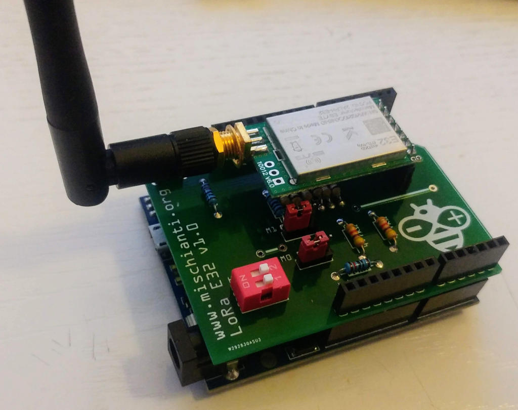
You can order the PCB [here](https://www.pcbway.com/project/shareproject/LoRa_E32_Series_device_Arduino_shield.html?from=mischianti05)
Instruction and assembly video on 6 part of the guide
# An WeMos D1 shield to simplify the use
WeMos D1 shield
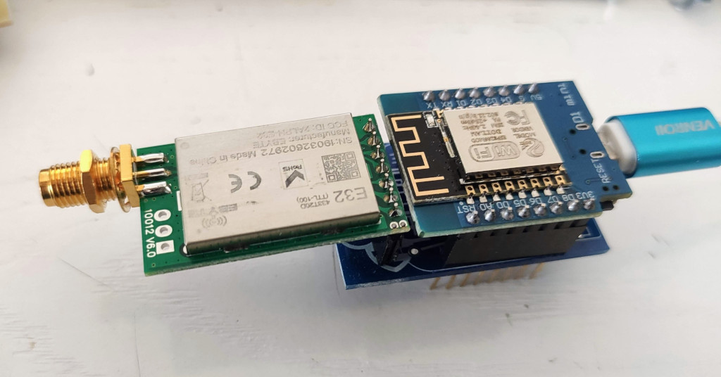
You can order the PCB [here](https://www.pcbway.com/project/shareproject/LoRa_E32_Series_device_WeMos_D1_mini_shield_RF_8km_range.html?from=mischianti05)
# An ESP32 shield to simplify the use
ESP32 shield
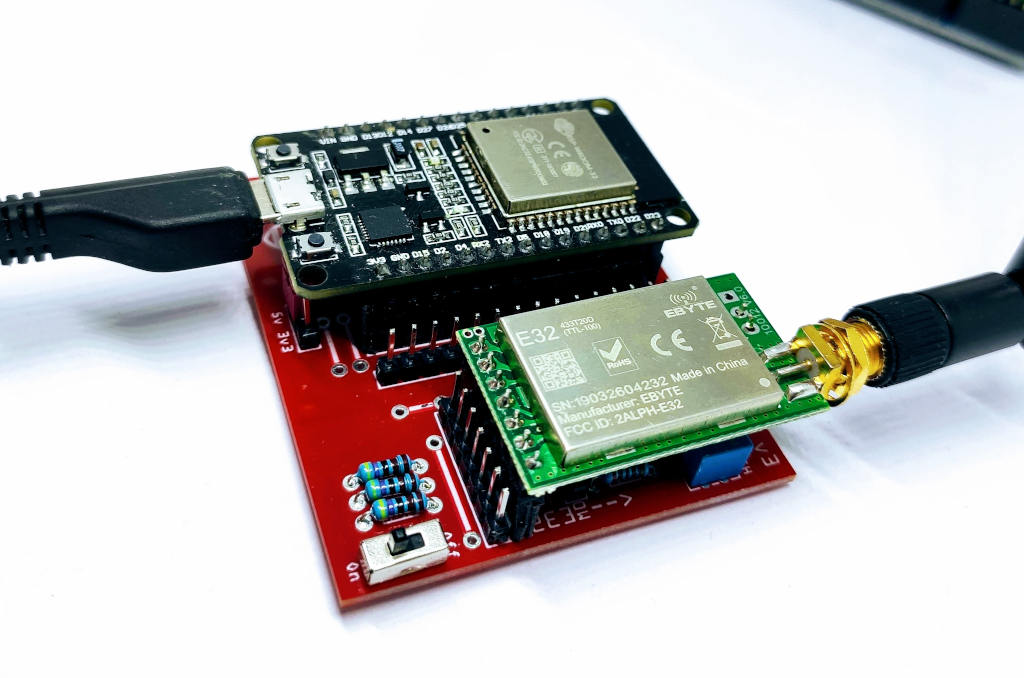
You can order the PCB [here](https://www.pcbway.com/project/shareproject/LoRa_ESP32_DEV_KIT_v1_shield_for_EByte_E32_E22__RF_8km_12km_range.html?from=mischianti05)
Instruction and assembly video on 6 part of the guide
# LoRa E32 (EBYTE LoRa SX1278/SX1276) series Library for Arduino, esp8266 and esp32-
I create a library to manage EBYTE E32 series of LoRa device, very powerfull, simple and cheap device.
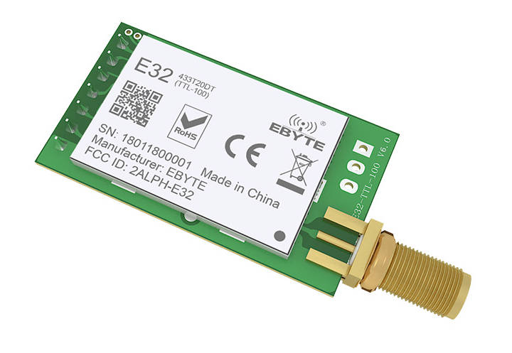
LoRa E32-TTL-100
You can find here [AliExpress (3Km device)](http://s.click.aliexpress.com/e/eOHotRkU) [AliExpress (8Km device)](http://s.click.aliexpress.com/e/qRuqOQQM)
They can work over a distance of 3000m to 8000m, and they have a lot of features and parameter.
So i create this library to simplify the usage.
Please refer to my article to get updated Schema
### Library
You can find my library here.
To download.
Click the DOWNLOADS button in the top right corner, rename the uncompressed folder LoRa_E32.
Check that the LoRa_E32 folder contains LoRa_E32.cpp and LoRa_E32.h.
Place the LoRa_E32 library folder your /libraries/ folder.
You may need to create the libraries subfolder if its your first library.
Restart the IDE.
#### Pinout

E32 TTL 100
You can buy here [AliExpress](http://s.click.aliexpress.com/e/eOHotRkU)
|Pin No.|Pin item|Pin direction|Pin application|
|---|---|---|---|
|1|M0|Input(weak pull-up)|Work with M1 & decide the four operating modes.Floating is not allowed, can be ground.|
|2|M1|Input(weak pull-up)|Work with M0 & decide the four operating modes.Floating is not allowed, can be ground.|
|3|RXD|Input|TTL UART inputs, connects to external (MCU, PC) TXD outputpin. Can be configured as open-drain or pull-up input.|
|4|TXD|Output|TTL UART outputs, connects to external RXD (MCU, PC) inputpin. Can be configured as open-drain or push-pull output|
|5|AUX|Output|To indicate module’s working status & wakes up the external MCU. During the procedure of self-check initialization, the pin outputs low level. Can be configured as open-drain output orpush-pull output (floating is allowed).|
|6|VCC|Power supply 2.3V~5.5V DC|
|7|GND|Ground|As you can see you can set various modes via M0 and M1 pins.|
|**Mode**|**M1**|**M0**|**Explanation**|
|---|---|---|---|
|Normal|0|0|UART and wireless channel is good to go|
|Wke-Up|0|1|Same as normal but a preamble code is added to transmitted data for waking-up the receiver.|
|Power-Saving|1|0|UART is disable and wireless is on WOR(wake on radio) mode which means the device will turn on when there is data to be received. Transmission is not allowed.|
|Sleep|1|1|Used in setting parameters. Transmitting and receiving disabled.|
As you can see there are some pins that can be use in a static way, but If you connect It to the library you gain in performance and you can control all mode via software, but we are going to explain better next.
### Fully connected schema
As I already say It’s not important to connect all pin to the output of microcontroller, you can put M0 and M1 pins to HIGH or LOW to get desidered configuration, and **if you don’t connect AUX the library set a reasonable delay to be sure that the operation is complete**.
#### AUX pin
When transmitting data can be used to wake up external MCU and return HIGH on data transfer finish.
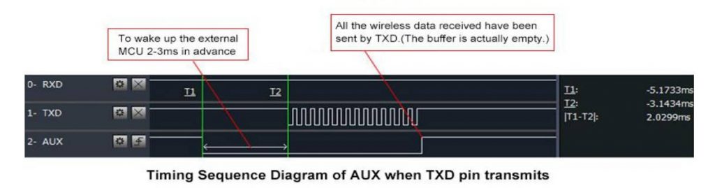
LoRa E32 AUX Pin on transmission
When receiving AUX going LOW and return HIGH when buffer is empty.

LoRa e32 AUX pin on reception
It’s also used for self checking to restore normal operation (on power-on and sleep/program mode).
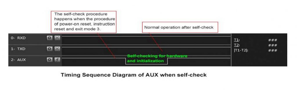
LoRa e32 AUX pin on self-check
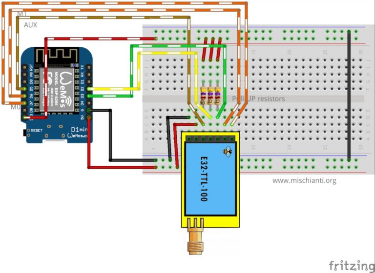
esp8266 connection schema is more simple because It work at the same voltage of logical communications (3.3v).

LoRa E32 TTL 100 Wemos D1 fully connected
It’s important to add pull-up resistor (4,7Kohm) to get good stability.
|M0|D7|
|---|---|
|M1|D6|
|RX|PIN D2 (PullUP 4,7KΩ)|
|TX|PIN D3 (PullUP 4,7KΩ)|
|AUX|D5 (Input)|VCC|
|3.3v|GND|GND|
Arduino working voltage is 5v, so we need to add a voltage divider on RX pin M0 and M1 of LoRa module to prevent damage, you can get more information here [Voltage divider: calculator and application](https://www.mischianti.org/2019/06/15/voltage-divider-calculator-and-application/).
You can use a 2Kohm resistor to GND and 1Kohm from signal than put together on RX.

LoRa E32 TTL 100 Arduino fully connected
|M0|7 (Voltage divider)|
|---|---|
|M1|6 (Voltage divider)|
|RX|PIN D2 (PullUP 4,7KΩ & Voltage divider)|
|TX|PIN D3 (PullUP 4,7KΩ)|
|AUX|5 (Input)|
|VCC|3.3v|
|GND|GND|
#### Basic configuration option
|ADDH|High address byte of module (the default 00H)|00H-FFH|
|---|---|---|
|ADDL|Low address byte of module (the default 00H)|00H-FFH|
|SPED|Information about data rate parity bit and Air data rate|CHAN|
|Communication channel(410M + CHAN*1M), default 17H (433MHz), **valid only for 433MHz device**|00H-1FH|
|---|---|
OPTION
Type of transmission, pull-up settings, wake-up time, FEC, Transmission power
#### SPED detail
UART Parity bit: _UART mode can be different between communication parties
|7|6|UART parity bit|Const value|
|---|---|---|---|---|
|0|0|8N1 (default)|MODE_00_8N1|
|0|1|8O1|MODE_01_8O1|
|1|0|8 E1|MODE_10_8E1|
|1|1|8N1 (equal to 00)|MODE_11_8N1|
UART baud rate: UART baud rate can be different between communication parties, The UART baud rate has nothing to do with wireless transmission parameters & won’t affect the wireless transmit / receive features.
|5|43|TTL UART baud rate(bps)|Constant value|
|---|---|---|---|
|0|0|0|1200|UART_BPS_1200|
|0|0|1|2400|UART_BPS_2400|
|0|1|0|4800|UART_BPS_4800|
|0|1|1|9600 (default)|UART_BPS_9600|
|1|0|0|19200|UART_BPS_19200|
|1|0|1|38400|UART_BPS_38400|
|1|1|0|57600|UART_BPS_57600|
|1|1|1|115200|UART_BPS_115200|
Air data rate: The lower the air data rate, the longer the transmitting distance, better anti- interference performance and longer transmitting time, The air data rate must keep the same for both communication parties.
|2|1|0|Air data rate(bps)|Constant value|
|---|---|---|---|---|
|0|0|0|0.3k|AIR_DATA_RATE_000_03|
|0|0|1|1.2k|AIR_DATA_RATE_001_12|
|0|1|0|2.4k (default)|AIR_DATA_RATE_010_24|
|0|1|1|4.8k|AIR_DATA_RATE_011_48|
|1|0|0|9.6k|AIR_DATA_RATE_100_96|
|1|0|1|19.2k|AIR_DATA_RATE_101_192|
|1|1|0|19.2k (same to 101)|AIR_DATA_RATE_110_192|
|1|1|1|19.2k (same to 101)|AIR_DATA_RATE_111_192|
#### OPTION detail
Transmission mode: in fixed transmission mode, the first three bytes of each user’s data frame can be used as high/low address and channel. The module changes its address and channel when transmit. And it will revert to original setting after complete the process.
|7|Fixed transmission enabling bit(similar to MODBUS)|Constant value|
|---|---|---|
|0|Transparent transmission mode|FT_TRANSPARENT_TRANSMISSION|
|1|Fixed transmission mode|FT_FIXED_TRANSMISSION|
IO drive mode: this bit is used to the module internal pull- up resistor. It also increases the level’s adaptability in case of open drain. But in some cases, it may need external pull-up
resistor.
|6|IO drive mode ( default 1)|Constant value|
|---|---|---|
|1|TXD and AUX push-pull outputs, RXD pull-up inputs|IO_D_MODE_PUSH_PULLS_PULL_UPS|
|0|TXD、AUX open-collector outputs, RXD open-collector inputs|IO_D_MODE_OPEN_COLLECTOR|
Wireless wake-up time: the transmit & receive module work in mode 0, whose delay time is invalid & can be arbitrary value, The transmitter works in mode 1 can transmit the preamble code of the corresponding time continuously, when the receiver works in mode 2, the time means the monitor interval time (wireless wake-up). Only the data from transmitter that works in mode 1 can be
received.
|5|4|3|wireless wake-up time|Constant value|
|---|---|---|---|---|
|0|0|0|250ms (default)|WAKE_UP_250|
|0|0|1|500ms|WAKE_UP_500|
|0|1|0|750ms|WAKE_UP_750|
|0|1|1|1000ms|WAKE_UP_1000|
|1|0|0|1250ms|WAKE_UP_1250|
|1|0|1|1500ms|WAKE_UP_1500|
|1|1|0|1750ms|WAKE_UP_1750|
|1|1|1|2000ms|WAKE_UP_2000|
FEC: after turn off FEC, the actual data transmission rate increases while anti- interference ability decreases. Also the transmission distance is relatively short, both communication parties must keep on the same pages about turn-on or turn-off FEC.
|2|FEC switch|Constant value|
|---|---|---|
|0|Turn off FEC|FEC_0_OFF|
|1|Turn on FEC (default)|FEC_1_ON|
Transmission power
You can change this set of constant by apply a define like so:
Applicable for **E32-TTL-100, E32-TTL-100S1, E32-T100S2.**
The external power must make sure the ability of current output more than 250mA and ensure the power supply ripple within 100mV.
Low power transmission is not recommended due to its low power supply
efficiency.
|1|0|Transmission power (approximation)|Constant value|
|---|---|---|---|
|0|0|20dBm (default)|POWER_20|
|0|1|17dBm|POWER_17|
|1|0|14dBm|POWER_14|
|1|1|10dBm|POWER_10|
Applicable for E32-TTL-500。
The external power must make sure the ability of current output more than 700mA and ensure the power supply ripple within 100mV.
Low power transmission is not recommended due to its low power supply efficiency.
|1|0|Transmission power (approximation)|Constant value|
|---|---|---|---|
|0|0|27dBm (default)|POWER_27|
|0|1|24dBm|POWER_24|
|1|0|21dBm|POWER_21|
|1|1|18dBm|POWER_18|
Applicable for E32-TTL-1W, E32 (433T30S), E32 (868T30S), E32 (915T30S)
The external power must make sure the ability of current output more than 1A and ensure the power supply ripple within 100mV.
Low power transmission is not recommended due to its low power supply
efficiency.
|1|0|Transmission power (approximation)|Constant value|
|---|---|---|---|
|0|0|30dBm (default)|POWER_30|
|0|1|27dBm|POWER_27|
|1|0|24dBm|POWER_24|
|1|1|21dBm|POWER_21|
You can configure Channel frequency olso with this define:
#### Normal transmission mode
Normal/Transparent transmission mode is used to send messages to all device with same address and channel.
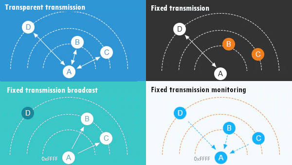
LoRa E32 transmitting scenarios, lines are channels
#### Fixed mode instead of normal mode
At same manner I create a set of method to use with fixed transmission
#### Fixed transmission
**You need to change only the sending method, because the destination device don’t receive the preamble with Address and Channel.**
Fixed transmission have more scenarios

## Thanks