Ecosyste.ms: Awesome
An open API service indexing awesome lists of open source software.
https://github.com/vascofazza/8bit-cpu
Schematics & code for my 74LS-based 8-bit MK1 CPU
https://github.com/vascofazza/8bit-cpu
74ls 8bit 8bit-cpu cpu electronics homemade mk1 mk1-computer mk1-cpu programming-board schematics
Last synced: 27 days ago
JSON representation
Schematics & code for my 74LS-based 8-bit MK1 CPU
- Host: GitHub
- URL: https://github.com/vascofazza/8bit-cpu
- Owner: vascofazza
- License: mit
- Created: 2020-03-01T20:02:38.000Z (over 4 years ago)
- Default Branch: master
- Last Pushed: 2022-12-12T06:42:16.000Z (over 1 year ago)
- Last Synced: 2024-02-18T17:35:01.035Z (4 months ago)
- Topics: 74ls, 8bit, 8bit-cpu, cpu, electronics, homemade, mk1, mk1-computer, mk1-cpu, programming-board, schematics
- Language: Python
- Homepage: https://hackaday.com/2020/12/31/diy-8-bit-computer-knows-all-the-tricks/
- Size: 21.7 MB
- Stars: 296
- Watchers: 29
- Forks: 23
- Open Issues: 6
-
Metadata Files:
- Readme: README.md
- License: LICENSE
Lists
- awesome-stars - vascofazza/8bit-cpu - Schematics & code for my 74LS-based 8-bit MK1 CPU (Python)
README
# MK1 8bit Computer
Schematics and code for my home-made 8-bit CPU and its companion boards.
Articles about this project:
[Hackaday.com](https://hackaday.com/2020/12/31/diy-8-bit-computer-knows-all-the-tricks/)
[Hackster.io](https://www.hackster.io/news/see-inside-of-a-cpu-with-the-mk1-8bit-computer-14fa9e313c73)
[InformaticaLab.com](https://blog.informaticalab.com/viaggio-allinterno-di-una-cpu-con-il-mk1-8bit-computer/)
## Overview
During the past month, I designed and built a programmable 8-bit CPU from scratch, out of basic series 74LS logic ICs.
This repository contains pictures, schematics, and code for this project and its companion boards.
* V 1.0 assembled:

* V 2.0b assembled:

- Helix Display Interface in action:

* V 1.0 in action:
**DEMO VIDEO (YouTube)**
[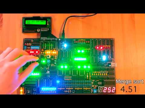](https://www.youtube.com/watch?v=qSviFkpLFKI)
## Architecture
The MK1 CPU is composed of several modules, all connected trough a common 8-bit BUS, the status of each module is shown by dedicated LEDs.
- The clock module is designed to allow step-by-step execution; in automatic mode the clock speed can be adjusted from 1Hz up to 32KHz.
- The computer programs are stored in RAM and the CPU can be programmed both manually, by inserting binary machine code through dip-switches, and automatically via a USB PC interface.
- The Programming interface is designed to be used in conjunction with an **Arduino Nano** or the **Start9** programming board.
- The **Start9** programming board allows the loading of multiple programs stored on an on-board flash memory without the aid of an external computer device.
- The Addressable memory space is 1024 byte, data, stack and code spaces are separated, the code address space is not writable.
- The instructions are variable-length (see **instruction-set [here](https://github.com/vascofazza/8bit-cpu/tree/master/MK1_CPU/programs/lib/mk1.cpu)**) 1 or 2 bytes long (first byte for the opcode, the second one for the argument), there are 4 general purpose registers (`A`, `B`, `C`, `D`) and a `stack pointer` register for subroutine calls.
- The **A**rithmetic **L**ogic **U**nit has a dedicated register for the second operand and supports the following operations:
- Addition
- Subtraction
- OR
- AND
- NOT
- Left/Right Shift
- Left/Right Rotation
- The Control Unit combinatory logic is implemented using EEPROMs (see **microcode [here](https://github.com/vascofazza/8bit-cpu/blob/master/MK1_CPU/code/microcode.txt)**) whilst each instruction is realized through a variable number of micro-instruction for a maximum of 6 micro-steps per instruction, including the fetch cycle. The instruction-set supports both direct and indirect memory access as well as absolute and conditional jumps on carry (`CF`) and zero (`ZF`) ALU flags.
- The computation output can be visualized on a 4-digit display, with a dedicated register, able to represent positive and 2-complement negative numbers both in decimal and hexadecimal format.
- The CPU can be extended thanks to the external BUS interface capable of handling up to 2 peripheral. The communication is bidirectional, the devices can send interrupts to the CPU to notify when new data is available. Interrupts are cleared once the data has been processed.
- The only available peripheral at the moment is the **Helix** display interface, an ATmega328-driven 2x16 LCD output display.
## Structure
- **MK1 CPU/**:
- **8bit-computer/**: KiCad project, schematics and PCB design of the **MK1 CPU**.
- **code/**:
- microcode.py: generates the binary EEPROM microcode.
- out_display.py: generates the binary output display EEPROM code.
- uploader.py: uploads a binary MK1 program to the CPU.
- mk1_computer_uploader/: Arduino programmer interface sketch.
- **assembler/**: fork of the hlorenzi's assembler, improved and customized for the MK1
- **programs/**: a collection of programs for the MK1 CPU plus the assembler definition
- **start9_programming_interface/**:
- **programming_interface/**: KiCad project, schematics and PCB design of the **Start9** programming board.
- **code/start9_programming_interface/**: Arduino code for the programming interface.
- **helix_display_interface/**:
- **display_interface/**: KiCad project, schematics and PCB design of the **Helix** display interface board.
- **code/helix_display_interface/**: Arduino code for the display interface.
- **eeprom_programmer/**: KiCad project, schematics and PCB design of a simple Arduino-based eeprom programmer
- **bus_breakout/**: KiCad project, schematics and PCB design of the external bus connector breakout board.
## Changelog
##### V2.0d:
- minor hardware revision
- revisited PCB design
- new memory architecture, code memory section is read-only, stack and data live on separated spaces
##### V2.0b:
- minor hardware revision
- Variable-length instructions (1 or 2 bytes)
- new custom assembler, thanks to https://github.com/hlorenzi/customasm
- few new instructions
- revisited microcode and instruction-set
##### V2.0:
- 4 general purposes registers (A, B, C, D)
- Stack Pointer implemented as an up-down counter
- External interface and interrupt handling
- Output display decodes HEX and ASCII values
- Clock speed multipliers
- Control Unit extended with 4 EEPROMs
- Variable step microcode counter length (each instruction uses the minimum amount of micro-steps)
- revisited microcode and instruction-set
##### V1.0:
- Bugfixes.
- `HL` and `STK` address signals available in the `MAR` dip-switch.
##### V0.1:
- Initial release