https://github.com/ShrimpingIt/micropython-mcp230xx
Micropython I2C-based manipulation of the MCP series GPIO expander, derived from Adafruit_MCP230xx
https://github.com/ShrimpingIt/micropython-mcp230xx
Last synced: 8 months ago
JSON representation
Micropython I2C-based manipulation of the MCP series GPIO expander, derived from Adafruit_MCP230xx
- Host: GitHub
- URL: https://github.com/ShrimpingIt/micropython-mcp230xx
- Owner: ShrimpingIt
- License: agpl-3.0
- Created: 2017-07-04T14:44:21.000Z (over 8 years ago)
- Default Branch: master
- Last Pushed: 2021-10-21T13:54:15.000Z (about 4 years ago)
- Last Synced: 2024-11-07T21:42:14.547Z (about 1 year ago)
- Language: Python
- Size: 53.7 KB
- Stars: 30
- Watchers: 5
- Forks: 16
- Open Issues: 5
-
Metadata Files:
- Readme: README.md
- License: LICENSE.md
Awesome Lists containing this project
- awesome-mpython - micropython-mcp230xx - Driver for MCP23017 and MCP23008 GPIO expanders. (精选驱动库 / 功能类)
- awesome-micropython - micropython-mcp230xx - Driver for MCP23017 and MCP23008 GPIO expanders. (Libraries / IO)
README
# micropython-mcp230xx
Micropython I2C-based manipulation of the MCP series GPIO expanders MCP23017 and MCP23008, derived from the Adafruit_MCP230xx.py module of https://github.com/adafruit/Adafruit_Python_GPIO
This has been tested with ESP8266 running Micropython 1.8.7 on MCP23017 only, but hopefully works also for MCP23008 if you have one. Please post an issue if you have success.
To use, wire up the GPIO expander chip following this loom...
* MCP23017 Pins
* 9 => 3.3V supply
* 10 => GND
* 12 => ESP8266 GPIO5 (NodeMCU D1) [I2C SCL Signal]
* 13 => ESP8266 GPIO3 (NodeMCU D2) [I2C SDA Signal]
* 12 => 10kOhm resistor => 3.3V Supply [I2C SCL Pull-up]
* 13 => 10kOhm resistor => 3.3V Supply [I2C SDA Pull-up]
* 18 => 10kOhm resistor => 3.3V Supply [Reset pin in 'run' configuration]
Also choose the address of each MCP23017, e.g.
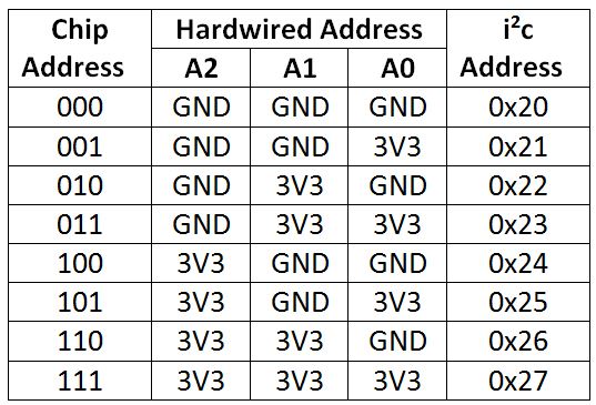
* Addressing pins for address 0x20
* 15 => 10kOhm resistor => GND
* 16 => 10kOhm resistor => GND
* 17 => 10kOhm resistor => GND
The mappings between pins and I2C addresses are...

If you wish to use a different I2C address, or a different GPIO-numbered SDA or SCL pin than the default then pass that in to the constructor.
The default constructor arguments mean that MCP23017() is equivalent to MPC23017(address=0x20, gpioScl=5, gpioSda=4).
A handy visual reference is this from mathworks, although I recommend that for ESP8266 the chip power should be provided by 3.3V not 5V, to make sure logic levels are correct and that the serial data line doesn't overload SDA.

For example, the following will set the output values of pins 10-15 and read the logic value (True or False) of pins 0-9
```python
import mcp
io = mcp.MCP23017()
# controls some output pins
outPins = list(range(10,16))
nextVals = {}
for pinNum in outPins:
io.setup(pinNum, mcp.OUT)
nextVals[pinNum] = True
io.output_pins(nextVals)
# monitors and prints some input pins
inPins = list(range(0,10))
for pinNum in inPins:
io.setup(pinNum, mcp.IN)
while True:
print(io.input_pins(inPins))
```