https://github.com/alan-kudelko/drinkcreator6000
https://github.com/alan-kudelko/drinkcreator6000
c-plus-plus cpp embedded hardware
Last synced: about 1 year ago
JSON representation
- Host: GitHub
- URL: https://github.com/alan-kudelko/drinkcreator6000
- Owner: alan-kudelko
- License: mit
- Created: 2025-06-24T03:59:19.000Z (about 1 year ago)
- Default Branch: main
- Last Pushed: 2025-07-08T12:44:31.000Z (about 1 year ago)
- Last Synced: 2025-07-08T13:55:11.071Z (about 1 year ago)
- Topics: c-plus-plus, cpp, embedded, hardware
- Language: C++
- Homepage:
- Size: 3.73 MB
- Stars: 0
- Watchers: 0
- Forks: 0
- Open Issues: 1
-
Metadata Files:
- Readme: README.md
- License: LICENSE
Awesome Lists containing this project
README
# DrinkCreator6000 – RTOS System on Custom AVR Board
DrinkCreator6000 is a real-time operating system (RTOS) project designed for a custom-built drink dispensing machine powered by an AVR microcontroller and FreeRTOS. The system is entirely based on static memory allocation for robustness and predictability, and integrates multiple hardware modules for a fully functional beverage control unit.
The machine is powered by a standard 400W ATX power supply, which provides stable 5V and 12V rails for the logic circuitry, Peltier cooling modules, and peristaltic pumps used for dispensing liquids. Pumps are controlled via a 74HC595 shift register, which expands digital output lines and drives MOSFET transistors to switch the high-current 12V loads safely and efficiently.
Temperature is regulated using Peltier elements coupled with an internal water cooling system, enclosed within the device chassis for thermal efficiency and thermal isolation.
User input is handled via an MCP23017 I²C I/O expander, which generates interrupts only when button states change and buffers the last known button state — minimizing CPU load and improving responsiveness. System status, temperature data, and diagnostics are displayed on a 2004 character LCD screen driven over the I²C bus, allowing real-time monitoring directly from the front panel.
> 🔧 Status: In development
> 🧪 Goal: Create a fully functional, physical drink machine and explore structured multi-tasking using FreeRTOS AVR MCU.
---
## 🧠 Design Goals
- 🎯 Explore real-time scheduling and modular task separation
- 💾 Use 100% static memory allocation (no malloc, no heap)
- 🧰 Track system stability via runtime task/memory debug tools
- 🔁 Ensure recovery after failure using EEPROM fault logging
- 📟 Provide full system visibility through LCD diagnostics and monitoring
- 🧪 Serve as a practical testbed for FreeRTOS and embedded RTOS design
- 📚 Designed as an educational project to deepen understanding of multitasking, resource sharing, and fail-safe system design embedded systems
- 🧩 Implement low-level memory management techniques for optimized and reliable resource control
---
## 🧱 System Overview
The system is built around a custom-designed PCB featuring an ATmega2561 microcontroller. It uses FreeRTOS to run multiple independent tasks that manage the user interface, inputs, outputs, and internal logic.
Each screen or function (like selecting a drink or diagnostics) is handled by a dedicated software module. The interface guides the user through clear prompts, while internal tasks manage precise timing, input handling, and output control behind the scenes.
Key characteristics:
- Modular design for easy debugging and future expansion
- Fully statically allocated tasks for high reliability
- Built-in protection mechanisms against system faults
- Designed for responsiveness and predictable behavior
---
## 🖼️ Visual Overview
This section provides a visual presentation of the DrinkCreator6000 project, including photographs of the assembled machine, its hardware components, and screenshots illustrating the system’s operation. It aims to deliver a comprehensive understanding of the device’s physical design and functional behavior.
### 🎬 UI interface Demo
[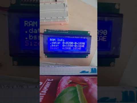](https://www.youtube.com/watch?v=Mg_Gc56w8Ac)
### 🎬 Project Demo
(Will be here soon)
---
## 📟 UI Flow & Screens
| ID | Screen | Description |
|----|----------------------|-----------------------------------------------------------------------------|
| 0 | **Welcome Screen** | Displays the project name, firmware version, and boot count. |
| 1 | **Drink Select Screen** | Shows the current drink name, ingredients, and related info. |
| 2 | **Drink Order Screen** | Displays dispensing progress, drink name, and ETA. |
| 3 | **Show Info Screen** | Displays general system status including uptime, firmware version, boot count, author, freezer temperature, RAM usage, and task stack diagnostics. |
| 4 | **Show Task Stack Info Screen** | Displays detailed information about FreeRTOS task stacks, including task names, priorities, and high-water marks (minimum remaining stack). |
| 5 | **Show Last Error Screen** | Displays last unconfirmed error stored in EEPROM |
Screen transition diagram:
╔════════════════════╗
║Drink Creator 6000 ║
0 Welcome Screen ║Initializing... ║
║Please wait ║
║[#####-----] 50 % ║
╚════════════════════╝
║
║
▼ 2 Drink Order Screen Submenu[1]
╔════════════════════╗ ╔════════════════════╗ ╔════════════════════╗
║[01]Test Drink ║ ║[01]Test Drink ║ Submenu[1] ║[01]Test Drink ║
1 Drink Select Screen ║Whiskey 50[ml]║ ═ ═ ═ ═ > ║ ║ ---------> ║ ║
║Rum 100[ml]║ ║Please wait... ║ ║Done! ║
║Cola 250[ml]║ ║[########--] 82% ║ ║[##########] 100% ║
╚════════════════════╝ ╚════════════════════╝ ╚════════════════════╝
║
║ +<----------------------------------------------------------------------------------------------------------------------------------------------------------------------------------<+
║ | |
▼ ▼ |
╔════════════════════╗ ╔════════════════════╗ ╔════════════════════╗ ╔════════════════════╗ ╔════════════════════╗ ╔════════════════════╗ |
║Drink Creator 6000 ║ Submenu[1] ║Drink Creator 6000 ║ Submenu[2] ║Drink Creator 6000 ║ Submenu[3] ║RAM Info ║ Submenu[4] ║RAM Info ║ Submenu[5] ║RAM Info ║ |
3 Show System Info[0] ║Software ver. 3.0 ║ ---------> ║Current run time ║ ---------> ║T: 21.2°C S:11.0°C ║ ---------> ║Usage: 6722 B/8192 B║ ---------> ║.data: 0x0200-0x1522║ ---------> ║HEAP: 0x1BF7-0x1BF7║ ----->+
║Author: Alan Kudelko║ ║21 days 19 h ║ ║Hyst: 4.0°C ║ ║[########--] 82% ║ ║.bss: 0x1522-0x1BF7║ ║STACK: 0x21B5-0x21FF║
║Startup count: 1000 ║ ║39 min 22 s ║ ║Status: Cooling ║ ║ ║ ║Size: 4898 B 1749 B║ ║Size: 0 B 74 B║
╚════════════════════╝ ╚════════════════════╝ ╚════════════════════╝ ╚════════════════════╝ ╚════════════════════╝ ╚════════════════════╝
║
║
▼
╔════════════════════╗ ╔════════════════════╗
║[03]Task information║ Submenu[1] ║[03]Task information║
4 Show Task Stack Info ║UPDATE SCREEN ║ ---------> ║####################║
║Highwater mark: 100║ ║ MEMORY CORRUPTED ║
║PR:1 State:Suspended║ ║####################║
╚════════════════════╝ ╚════════════════════╝
║
║ +<-------------------------------------------+
║ | |
▼ ▼ |
╔════════════════════╗ ╔════════════════════╗ |
║Stack overflow in t:║ Submenu[1] ║Error confirmed ║ |
5 Show Last Error ║Error time signature║ ---------> ║EEPROM updated ║ ----->+
║21 days 19 h ║ ║ ║
║39 min 22 s ║ ║ ║
╚════════════════════╝ ╚════════════════════╝
║
║
▼
╔════════════════════╗ ╔════════════════════╗
║HW Testing Mode ║ Submenu[1] ║HW Testing Mode ║
6 Test hardware ║Pumps Test Menu ║ ---------> ║Pumps Test Menu ║
║Pump ID: 12345678 ║ ║Pump ID: 12345678 ║
║Status: 0b00000011 ║ ║Status: 0b00000011 ║
╚════════════════════╝ ╚════════════════════╝
---
## 🗺️ Roadmap
- ✅ Create custom PCB with AVR MCU and additional components
- ✅ Create functions for static allocation of Queues, Mutexes, and Semaphores
- ✅ Create function for displaying current RAM usage via serial monitor
- ✅ Create function for debugging the last unconfirmed error stored in EEPROM
- ✅ Create function for displaying the boot count from EEPROM via serial port
- ✅ Create stackOverflowHook for handling stack overflow errors
- ✅ Create task for handling critical system errors such as stack overflows and logging them to EEPROM
- ✅ Create task for debugging stack usage and runtime status of all tasks via serial monitor
- ✅ Create main task for coordinating other tasks
- ✅ Create task for handling regular LCD updates
- ✅ Create task for regulating temperature inside the freezer
- 🔄 Create task for handling keyboard input from MCP23017 with software debounce
- 🔄 Create task for selecting the drink to be ordered
- ✅ Create welcome screen task to display a greeting message with project name, version, and boot count on the LCD at system startup
- 🔄 Create task for processing the ordered drink (pump activation)
- ✅ Create task to display project information such as author, startup count, and current runtime
- ✅ Implement software guard zones between task stacks for added protection and reliability
- ✅ Review .map file and optimize memory by efficient variable placement using linker script (.ld file)
- ✅ Create a custom memory segment named .tdat to store Task Control Blocks (TCBs), task stacks, and stack guard zones by modifying the linker script (.ld file)
- ✅ Implement a guard zone watchdog inside taskErrorHandler to detect guard zone corruption, indicating potential stack overflows
- ✅ Separate code into multiple files for better readability
- 🔄 Add EEPROM-based drink recipe loading at startup
- 🔄 Add automatic system reset after fatal system error (e.g. guard zone or memory corruption)
- 🔄 Implement stopPumps() function to safely disable all pump outputs
- 🔄 Implement stopCooler() function to safely disable the cooling system
---
## ⚙️ Technical Overview
### 1. 🛠️ Hardware and Libraries Requirements
#### 1.1 Hardware
- ATmega2560 / ATmega2561 microcontroller — or an Arduino Mega board for prototyping convenience
- LCD 2004 display with I²C backpack (e.g., based on HD44780, PCA9633, or AiP31068)
- 74HC595 shift register for pump control
- PCF8574N I²C I/O expander for keypad
#### 1.2 Software
- Arduino IDE (used for development and uploading)
- Arduino FreeRTOS library (adds multitasking and RTOS features)
- LiquidCrystal_I2C library (compatible with the I²C LCD driver used)
- avr-libc (AVR C runtime, typically included with Arduino toolchain)
---
### 2. 🧵 Task Overview
| Task ID | Task Name | Description | Priority | Stack Size | Free Stack |
|---------|----------------------------|---------------------------------------------------------------------------------------------------------------------------|----------|------------|------------|
| 00 | `taskErrorHandler` | Handles critical faults such as stack overflows and guard zone corruption, and logs errors to EEPROM | 3 | 256 | 50 |
| 01 | `taskSerialSystemDebugger` | Monitors stack and RAM usage across all tasks and outputs the data to the serial port | 1 | 270 | 47 |
| 02 | `taskMain` | Coordinates the system, manages high-level logic, activates tasks, and handles the current UI context | 1 | 200 | 129 |
| 03 | `taskReadInput` | Reads keyboard data from the MCP23017 I²C I/O expander | 2 | 150 | 75 |
| 04 | `taskSerialInput` | Simulates keyboard input via the serial port for debugging or testing purposes | 2 | 150 | 46 |
| 05 | `taskUpdateScreen` | Periodically updates the LCD based on current context of the systems | 1 | 250 | 55 |
| 06 | `taskReadTemp` | Reads the current temperature inside the freezer and updates a global variable | 1 | 180 | 118 |
| 07 | `taskRegulateTemp` | Regulates temperature based on the current readings and configured thresholds | 1 | 180 | 118 |
| 08 | `taskSelectDrink` | Handles drink selection logic and displays in on the LCD | 1 | 270 | 95 |
| 09 | `taskOrderDrink` | Controls the 74HC595 shift register and pump sequence when processing a drink order | 1 | 320 | 175 |
| 10 | `taskShowSystemInfo` | Displays various system statuses—RAM usage, temperature, task states, boot count, uptime, and last saved error—on the LCD | 1 | 300 | 80 |
| 11 | `taskWelcomeScreen` | Displays a decorative welcome screen to give the system a more professional appearance | 1 | 222 | 42 |
| 12 | `taskTestHardware` | Allows for testing of individual pumps, cooling fan, Peltier elements (Not implemented yet) | 1 | 222 | - |
*Note:*
- Task stacks will be fine-tuned in the final release
- taskWelcomeScreen and taskTestHardware share the same TCB and stack, as the former is deleted after execution. This reuse is necessary due to limited RAM (~800 bytes remaining). This setup also helps me better understand the behavior of task stack/TCB reuse in constrained memory environments
---
### 3. 📊 RAM Usage Overview (Start, End, Size)
| Region | Start Address | End Address | Size (bytes) |
|-----------|---------------|-------------|--------------|
| .data | 0x0200 | 0x0B08 | 2312 |
| .bss | 0x0B08 | 0x10AC | 1444 |
| .tdat | 0x10AC | 0x1EB0 | 3588 |
| Heap | 0x1BF7 | 0x1BF7 | 0 |
| CPU Stack | 0x21B5 | 0x21FF | 154 |
**Total free memory:** 836 bytes
*Note:*
- FreeRTOS task stacks are statically allocated and included within the `.tdat` segment.
- The CPU Stack refers to the main processor stack (used before the scheduler starts), not individual task stacks.
---
### 4. 💾 EEPROM Memory Map
| Address (hex) | Size (bytes) | Description |
|---------------|--------------|-----------------------------------|
| 0x0000 | 1 | Number of drinks in memory (n) |
| 0x0001 | 34 * n | Drinks data (n ≤ 26) |
| 0x0400 | 4 | Temperature set in freezer |
| 0x0404 | 4 | Temperature hysteresis width |
| 0x0800 | 135 | Last saved error |
| 0x0C00 | 2 | Bootups count |
---
### 5. Navigation & UI Context
Navigation within the user interface is managed through a global structure named UI_Context. This structure enables switching between different tasks by activating or deactivating them as necessary. The core control and navigation logic is implemented in the taskMain function.
The UI_Context structure is defined as follows:
UI_Context{
uint8_t autoScrollEnable: 1; // Enables (1) or disables (0) auto-scrolling of the submenu
uint8_t currentTask: 3; // Currently active task bound to the LCD (0 – 7)
uint8_t currentMenu: 3; // Currently selected menu within the task (0 – 7)
uint8_t currentSubMenu; // Currently selected submenu (0 - 255)
}
This structure stores information about the currently active task — the task responsible for updating the LCD by sending data via a queue to taskUpdateScreen(). It also tracks the currently selected menu and submenu within that task, providing a flexible and memory-efficient mechanism for UI navigation.
When a button is pressed (or a command is simulated via the serial port), taskMain evaluates whether a context switch is necessary. If so, it sends a task notification with a specific value (0 or 1) indicating whether the task should be deactivated or activated.
Upon receiving a deactivation notification, the affected task safely stops its execution. Then, taskMain updates the UI_Context accordingly and notifies the new task to begin its operation.
An example of this control logic is shown below:
if((*keyboardInput&E_GREEN_BUTTON)==E_GREEN_BUTTON){
taskENTER_CRITICAL();
UI_Context->currentTask=DRINK_ORDER;
UI_Context->currentMenu=0;
UI_Context->currentSubMenu=0;
taskEXIT_CRITICAL();
}
if((*keyboardInput&E_LWHITE_BUTTON)==E_LWHITE_BUTTON){
UI_Context->currentSubMenu--;
xTaskNotify(taskHandles[TASK_SELECT_DRINK],1,eSetValueWithOverwrite);
}
if((*keyboardInput&E_RWHITE_BUTTON)==E_RWHITE_BUTTON){
UI_Context->currentSubMenu++;
xTaskNotify(taskHandles[TASK_SELECT_DRINK],1,eSetValueWithOverwrite);
}
if((*keyboardInput&E_BLUE_BUTTON)==E_BLUE_BUTTON){
taskENTER_CRITICAL();
UI_Context->currentTask=SHOW_INFO;
UI_Context->currentMenu=0;
UI_Context->currentSubMenu=0;
taskEXIT_CRITICAL();
xTaskNotify(taskHandles[TASK_SHOW_SYS_INFO],1,eSetValueWithOverwrite);
xTaskNotify(taskHandles[TASK_SELECT_DRINK],0,eSetValueWithOverwrite);
}
*Note:*
- When modifying multiple fields of the UI_Context structure, it is crucial to ensure the operation is "atomic". This means preventing context switches by the scheduler during the update (e.g., by entering a critical section). Without proper protection, concurrent access to UI_Context by multiple tasks may lead to inconsistent states or subtle race conditions that are difficult to debug.
---
### 6. Input Handling & MCP23017
#### 6.1 Configuration of MCP23017
The MCP23017 is a 16-bit I/O expander IC that provides additional GPIO pins via an I2C interface. It features 22 registers (comprising 11 register pairs) that enable control of 16 pins, organized into two 8-bit ports (Port A and Port B). Its primary advantage lies in its ability to expand the number of input and output lines available to a microcontroller.
However, this IC was selected due to its inclusion of two interrupt pins, which can be utilized to signal when a button press occurs. Moreover, it maintains the previous button states within dedicated registers, allowing the interrupt to be serviced at a later time without the need for immediate response. The stored button states persist until the data is read from the device, ensuring no input events are lost.
#### 6.2 Reading data from MCP23017
---
### 7. Project Structure & File Overview
```
📦 DrinkCreator6000/
│
├── Datasheets/ # Documentation of used ICs
├── DrinkCreator6000.ino # Arduino IDE project file
│
├── DrinkCreator6000_Config.cpp
├── DrinkCreator6000_Config.h # Project-wide configuration and variable declarations
│
├── DrinkCreator6000_Init.cpp
├── DrinkCreator6000_Init.h # Hardware, IO, and memory initialization functions
│
├── DrinkCreator6000_Tasks.h # Definitions of all tasks
├── DrinkCreator6000_CustomData.h # User-defined data types
├── DrinkCreator6000_EEPROM.h # EEPROM management functions
│
├── taskErrorHandler.cpp
├── taskErrorHandler.h
├── ... # Other task source/header files
│
├── Custom_Linker.ld # Linker script with custom sections
│
├── README.md # Project overview
└── LICENSE # License file
```
---
### 8. Memory Layout & Custom Segments
#### 8.1 Memory Layout

- `__data_start` is a linker symbol representing the starting address of the `.data` section in SRAM on AVR microcontrollers.
- `__data_end` is a linker symbol representing the ending address of the `.data` section in SRAM on AVR microcontrollers.
- `__bss_start` is a linker symbol representing the starting address of the `.bss` section in SRAM on AVR microcontrollers.
- `__bss_end` is a linker symbol representing the ending address of the `.bss` section in SRAM on AVR microcontrollers.
- `__tdat_start` is a linker symbol representing the starting address of the `.tdat` section in SRAM.
- `__tdat_end` is a linker symbol representing the ending address of the `.tdat` section in SRAM.
- `__heap_start` is a linker symbol representing the starting address of the heap section in SRAM.
- `__heap_end` is a C variable defined by me to represent the current end of the heap. Its value is calculated at runtime (see Notes below).
- `__stack_ptr` is a C variable defined by me to capture the initial value of the stack pointer before the RTOS scheduler starts (see Notes below).
- `RAMEND` is a predefined constant representing the last address of SRAM on AVR microcontrollers. For the ATmega2561 used in this project, `RAMEND` is equal to `0x21FF`.
*Note:*
- The `.tdat` section is a custom memory segment defined in the linker script. It is used to store Task Control Blocks (TCBs), task stacks, and associated guard zones. By placing all task stacks contiguously within .tdat, the system ensures controlled stack allocation and simplifies stack overflow detection.
- The symbols `__tdat_start` and `__tdat_end` were predefined in the linker script, along with a custom `.tdat` section. This section is used to store Task Control Blocks (TCBs), task stacks, and corresponding guard zones. The `.tdat` section ensures that stacks and their guard zones are placed contiguously in memory, enabling reliable stack overflow monitoring.
- The `__heap_end` variable is computed as:
__heap_end = (__brkval != 0) ? __brkval : (void*)&__heap_start;
- `__brkval` is a pointer internally managed by malloc() to indicate the current top of the heap. If no memory has been allocated yet, it remains zero.
- The `__stack_ptr` variable is initialized with the value of the `SP` register before the RTOS scheduler starts. On AVR microcontrollers, `SP` holds the current stack pointer. However, after the scheduler starts, `SP` is overwritten with the stack pointer of the currently executing task, which would lead to incorrect free memory calculations if used directly.
#### 8.2 Custom Segments
When compiling a program, the linker is responsible for placing variables and code into the correct memory segments — for example, initialized variables go into the `.data` section, uninitialized variables into `.bss`, and so on. This process is usually handled automatically by the default linker script.
However, relying solely on the default script does not guarantee that specific variables will be placed contiguously in memory. Their placement can vary depending on factors such as the order of .o files passed to the linker.
To ensure that all data related to each task — specifically the Task Control Block (TCB), task stack, and its corresponding guard zone — are placed contiguously in memory, I defined a custom .tdat memory section. This section is further divided into subsections, one for each stack and guard zone. This layout allows for reliable and predictable stack overflow detection, as a dedicated task can systematically inspect each guard zone to verify memory integrity.
I chose to manually assign each guard zone and task stack to its own subsection in the linker script to ensure strict ordering and prevent unexpected memory layout issues. This eliminates any ambiguity and guarantees that variables appear exactly where intended in SRAM.
This configuration is reflected in the following linker script fragment:
.tdat (NOLOAD) :
{
. = ALIGN(1);
PROVIDE (__tdat_start = . );
KEEP(*(.tdat.guardZone0));
KEEP(*(.tdat.errorHandlerStack));
KEEP(*(.tdat.guardZone1));
KEEP(*(.tdat.serialSystemDebuggerStack));
KEEP(*(.tdat.guardZone2));
KEEP(*(.tdat.mainStack));
KEEP(*(.tdat.guardZone3));
KEEP(*(.tdat.readInputStack));
KEEP(*(.tdat.guardZone4));
KEEP(*(.tdat.serialInputStack));
KEEP(*(.tdat.guardZone5));
KEEP(*(.tdat.updateScreenStack));
KEEP(*(.tdat.guardZone6));
KEEP(*(.tdat.readtempStack));
KEEP(*(.tdat.guardZone7));
KEEP(*(.tdat.regulateTempStack));
KEEP(*(.tdat.guardZone8));
KEEP(*(.tdat.selectDrinkStack));
KEEP(*(.tdat.guardZone9));
KEEP(*(.tdat.orderDrinkStack));
KEEP(*(.tdat.guardZone10));
KEEP(*(.tdat.showSystemInfoStack));
KEEP(*(.tdat.guardZone11));
KEEP(*(.tdat.welcomeScreenStack));
KEEP(*(.tdat))
KEEP(*(.tdat*))
PROVIDE (__tdat_end = . );
}
Below is an example of how a guard zone and a task stack are declared in code:
volatile StackType_t guardZone0[GUARD_ZONE_SIZE] __attribute__((section(".tdat.guardZone0")));
StackType_t errorHandlerStack[TASK_ERROR_HANDLER_STACK_SIZE] __attribute__((section(".tdat.errorHandlerStack")));
*Note:*
- Each guard zone is declared as volatile to ensure the compiler does not optimize away accesses or overwrite them unexpectedly. Since these memory regions are checked explicitly in software for integrity (e.g., to detect overflow), they must always be preserved exactly as written in memory. Marking them as volatile prevents the compiler from assuming they remain unchanged or unused.
After compiling and inspecting the .map file, I confirmed that the .tdat section is correctly placed in SRAM. All subsections appear in the exact order defined in the linker script, starting from `__tdat_start`. Each stack and guard zone is properly aligned and located contiguously, which is essential for deterministic overflow detection logic.
.tdat 0x008010e8 0xe97
0x008010e8 . = ALIGN (0x1)
0x008010e8 PROVIDE (__tdat_start, .)
*(.tdat.guardZone0)
.tdat.guardZone0
0x008010e8 0x20 C:\Users\kujon\AppData\Local\Temp\ccjR9wYB.ltrans0.ltrans.o
*(.tdat.errorHandlerStack)
.tdat.errorHandlerStack
0x00801108 0x100 C:\Users\kujon\AppData\Local\Temp\ccjR9wYB.ltrans0.ltrans.o
*(.tdat.guardZone1)
.tdat.guardZone1
0x00801208 0x20 C:\Users\kujon\AppData\Local\Temp\ccjR9wYB.ltrans0.ltrans.o
---
### 9. Free Memory Calculation
Free memory calculation is straightforward on AVR microcontrollers.
The stack starts at `RAMEND` and grows downward. Its current position is captured in the `__stack_ptr` variable, which holds the value of the `SP` (Stack Pointer) register before the RTOS scheduler is started.
The heap begins at `__heap_start`, which is the first available address after global and static data sections (`.data`, `.bss`, and `.tdat`) are initialized. It grows upward, with its current boundary given by `__heap_end`.
Therefore, the amount of free memory available in the system is calculated as:
Free memory = __stack_ptr - __heap_end
---
### 10. 🧩 PCB Layout
Preview of the custom-designed AVR board used in the project:


---
### 10. 🔌 Electrical Schematic
Full schematic of the system, including MCU, Peltier drivers, shift register control, keypad interface, and LCD wiring:
---
### 11. Additional Notes
---
### 12. 🚀 How to build
This project is built using the Arduino IDE. While it simplifies getting started, it comes with serious drawbacks — especially a lack of transparency and limited control over the toolchain, compared to more advanced environments like Atmel Studio.
Despite these limitations, the project currently compiles and uploads successfully through Arduino IDE. However, I plan to replace or augment the workflow with a custom build script that offers finer control over compilation and flashing.
What I can say for sure is that Arduino is a platform designed primarily for hobbyists. Had I been fully aware of its limitations earlier, I would have chosen to develop the project using a professional environment like Atmel Studio from the start — which would have saved a lot of time.
#### 12.1
#### 12.2
---