https://github.com/bmatcuk/arcaduinome
Arduino based MIDI controller using arcade buttons.
https://github.com/bmatcuk/arcaduinome
Last synced: about 1 month ago
JSON representation
Arduino based MIDI controller using arcade buttons.
- Host: GitHub
- URL: https://github.com/bmatcuk/arcaduinome
- Owner: bmatcuk
- License: other
- Created: 2014-05-30T04:45:45.000Z (about 12 years ago)
- Default Branch: master
- Last Pushed: 2014-10-20T01:20:08.000Z (over 11 years ago)
- Last Synced: 2025-01-05T22:27:51.658Z (over 1 year ago)
- Language: Arduino
- Size: 12.7 MB
- Stars: 2
- Watchers: 3
- Forks: 1
- Open Issues: 1
-
Metadata Files:
- Readme: README.md
- License: LICENSE
Awesome Lists containing this project
README
# arcaduinome
Arcaduinome is an [Arduino](http://www.arduino.cc/) based MIDI controller that uses arcade buttons for input. The name is a combination of Arcade, Arduino, and [Monome](http://monome.org/).
1. [Software](#software)
2. [Hardware](#hardware)
1. [Schematic](#schematic)
2. [Board PCB Layout](#board-pcb-layout)
3. [Arduino Firmware](#arduino-firmware)
4. [License](#license)
## Software
The ArduinoSketch directory contains the Arduino source code. It requires that you have the MIDI Library installed. The latest build (at time of writing) is included in this repo. You'll first need to install it into your Arduino app: Open the Arduino application and select Sketch -> Import Library -> Add Library, then select Arduino_MIDI_Library_v4.1.zip.
## Hardware
Arcaduinome is based around the [Arduino Uno](http://arduino.cc/en/Main/ArduinoBoardUno), third revision. Most of the other hardware components are to support the LEDs which light the arcade buttons. Each component links to a website where you could buy the part, but you can probably find most of these parts at a variety of distributors. A lot of these parts could be swapped out for similar parts. I've made some notes below about why I've chosen a specific part and whether or not you can use some other generic part.
Datasheets for some of these parts can be found in the `reference` directory of this repository.
* **[Arduino Uno R3](http://www.adafruit.com/products/50)**
I highly recommend a 3rd Revision (R3) board here. The R3 board has a larger USB-to-serial microcontroller (Atmega16U2) which will be reprogrammed later. If you have an older R1 or R2 board, you'll need to reprogram the USB-to-serial microcontroller every time you need to switch between MIDI and Arduino mode. Very annoying. With the R3, you just jumper two pins to switch back to Arduino mode.
* **16x [Sanwa OBSC 24 CW](http://www.paradisearcadeshop.com/sanwa-obsc-24mm-translucent-pushbuttons/689-sanwa-obsc-24-cw.html)**
Any arcade button will do. Sanwa buttons are extremely popular with arcade cabinet and fighting game enthusiasts for their quick response and high-reliability. However, the buttons might be the most expensive part, so you can save a bit with some cheaper buttons. Just make sure they are translucent/transparent.
* **[Protoshield for Arduino](http://www.adafruit.com/products/51)**
This part is optional. I like using the protoshield to break out the IO pins from the Arduino and it gives me a nice area to solder everything together. Plus, it's compact.
* **16x [Common Anode RGB LEDs](http://www.adafruit.com/products/302)**
Theoretically, any RGB LEDs will do, as long as they are common-anode. You may need to adjust resistor values depending on the forward voltage of the LEDs you pick. Link goes to a 25-pack that's actually cheaper, I've found, than buying 16 discrete LEDs from other distributors. So save some money and you'll have 9 extra LEDs for your next project! Woot!
* **[Sanken SLA5086 - 5x P-Channel FET Array](http://www.digikey.com/product-search/en?pv606=52&pv69=80&FV=fff40015%2Cfff80346&mnonly=0&newproducts=0&ColumnSort=0&page=1&stock=1&quantity=0&ptm=0&fid=0&pageSize=500)**
The P-Channel FETs are used on the "high-side" of the LEDs to turn on the "rows". FETs are well-suited for this switching application, specifically P-Channels for the high-side. If every LED in a row is turned on, the high-side switch must be able to source ~0.24A. This part can handle 5A, so no problems there. Additionally, this particular part has a low (logic level) gate-threshold voltage, which means that it should fully "turn on" easily from the Arduino IO pin. All around, a good fit, and the hardest part to find alternatives for, unless you don't mind dealing with surface mount components. We're only going to use 4 of the 5 PFETs in this package, since we only have 4 rows of LEDs. And we're also going to use these rows to multiplex our buttons. This way, we only need to use 4 inputs for the 16 buttons.
* **2x [STMicroelectronics STPIC6D595B1R 8-bit Shift Register](http://www.digikey.com/product-detail/en/STPIC6D595B1R/497-6328-5-ND/1762207)**
The shift registers are used on the "low-side" of the LEDs to control individual LEDs (ie, the columns). We need 2 of these because we have "12" LEDs per row (each RGB LED is basically like 3 LEDs - we have 4 RGB LEDs per row, so, 4 x 3 = 12). The two ICs are "daisy chained" to make a 16-bit shift register; we just ignore the last 4-bits since we only need 12. Each pin of the shift register must be able to sink 20mA, and, if every LED in the row is "on", the IC as a whole must be able to sink 8 x 20mA = 160mA. This IC can easily handle that with it's open-drain outputs. Additionally, the outputs are latched, which the code takes advantage of.
* **16x [NXP Semiconductors 1N4148,113 Standard Diode](http://www.digikey.com/product-detail/en/1N4148,113/568-1360-1-ND/763357)**
Use any standard diodes you want, though lower forward voltages are preferable. These are just used to ensure that the buttons don't interfere with each other if you press two at the same time... particularly if they are in different rows.
* **8x [120 Ohm Resistors](http://www.digikey.com/product-detail/en/CFM14JT120R/S120QCT-ND/2617666)**
Use any standard 120 Ohm resistors you like. These limit current through the green and blue sections of the RGB LEDs. If you use different RGB LEDs, make sure to use appropriate resistors! The RGB LEDs I'm using have a 3.2V forward voltage for the green and blue sections, so these resistors should limit current to somewhere around 15mA.
* **4x [220 Ohm Resistors](http://www.digikey.com/product-detail/en/CF14JT220R/CF14JT220RCT-ND/1830334)**
Use any standard 220 Ohm resistors you like. These limit current through the red section of the RGB LEDs. If you use different RGB LEDs, make sure to use appropriate resistors! The RGB LEDs I'm using have a 1.8V forward voltage for the red section, so these resistors should limit current to somewhere around 15mA.
* **9x 4.7 kOhm Resistors**
I had some of these laying around, so I don't have a link for them. The value is not very important, so any value around 4.7k is fine if you happen to have some resistors laying around, too. Though, you shouldn't have any trouble finding them on Digikey (or similar sites). These are just used as pull-up resistors for the Gates of the PFETs, and pull-down resistors for the buttons. The pull-up resistors will cause the PFETs to be shut-off when the circuit is first powered up, and the pull-down resistors will cause the Arduino to read 0's for the buttons until they are pressed. We need 5 of these resistors for the 5 PFETs in our array package (even though we are only using 4 of those PFETs, we want to make sure the 5th is "turned off"), and 4 resistors for the multiplexed buttons.
* **[12-pin SIP Socket](http://www.digikey.com/product-detail/en/643644-3/A29107-ND/294602)**
Socket for the P-Channel FET Array - if you decide on some other high-side solution, you might not need this.
* **2x [16-pin DIP Socket](http://www.digikey.com/product-detail/en/A16-LC-TR-R/AE9994-ND/821748)**
Sockets for the low-side shift registers - if you decide on some other low-side solution, you might not need this.
### Schematic
This is the full schematic for the Arcaduinome:
[](https://raw.githubusercontent.com/bmatcuk/arcaduinome/master/schematic.png)
However, due to limitations in the free version of Eagle and the fact that my PCB-manufacturer-of-choice is going to require that I order at least 3 boards anyway, I designed a smaller board that houses 4 buttons, with associated LEDs, resistors, and diodes, and a shift register:
[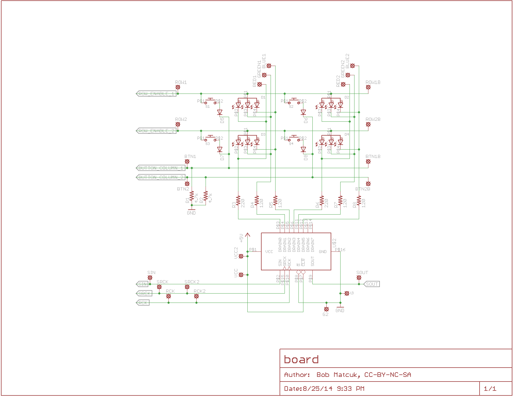](https://raw.githubusercontent.com/bmatcuk/arcaduinome/master/board.png)
The idea is that four of these boards would be used: the two boards at the "bottom" will house the shift registers. The two boards at the "top" will not have shift registers and, instead, use jumpers to connect to the boards on the "bottom". Similarly, jumpers are used to connect boards from left to right.
These schematics were generated using the free version of [Eagle v7.1](http://www.cadsoftusa.com/). The files are available in the `eagle` directory of this repository.
### Board PCB Layout
This is the layout of the smaller board I designed:
[](https://raw.githubusercontent.com/bmatcuk/arcaduinome/master/board_pcb.png)
This layout was generated using the free version of [Eagle v7.1](http://www.cadsoftusa.com/). The files are available in the `eagle` directory of this repository.
## Arduino Firmware
The Arduino Uno R3 uses a microcontroller, specifically the Atmega16U2, as a USB-to-Serial adapter. Arcaduinome takes advantage of this fact using the [Moco](http://morecatlab.akiba.coocan.jp/lab/index.php/aruino/midi-firmware-for-arduino-uno-moco/?lang=en) (aka dualMocoLUFA) firmware. The latest version (at the time of writing) is included in this repo as dualMoco.hex. Installing this firmware on the Atmega16U2 will cause the Arduino to appear as a generic MIDI device to Windows/OSX. This way, we won't need any special drivers to interface with Arcaduinome.
To install the firmware into the Atmega16U2, follow the [DFU Programming Directions](http://arduino.cc/en/Hacking/DFUProgramming8U2) on Arduino's website. Once the new firmware has been installed, it will appear as a generic MIDI device when connected to your computer. You will no longer be able to use it as an Arduino (in other words, you won't be able to reprogram it). However, if you want to reenable Arduino mode, disconnect the Arduino from your computer, connect a jumper between pin 4 and 6 on the ICSP header, and reconnect to your computer. It should now appear as a normal Arduino Uno. When you're done reprogramming, disconnect from your computer, remove the jumper, and reconnect - it will now appear as a MIDI device again!
## License
This work is licensed under a [Creative Commons Attribution-NonCommercial-ShareAlike 4.0 International License](http://creativecommons.org/licenses/by-nc-sa/4.0/)
[](http://creativecommons.org/licenses/by-nc-sa/4.0/)