Ecosyste.ms: Awesome
An open API service indexing awesome lists of open source software.
https://github.com/bwhitman/pushpin
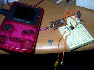
MIDI synthesizer for the Game Boy Color
https://github.com/bwhitman/pushpin
Last synced: about 2 months ago
JSON representation
MIDI synthesizer for the Game Boy Color
- Host: GitHub
- URL: https://github.com/bwhitman/pushpin
- Owner: bwhitman
- License: gpl-2.0
- Created: 2012-12-19T20:11:45.000Z (almost 12 years ago)
- Default Branch: master
- Last Pushed: 2021-07-12T22:19:29.000Z (about 3 years ago)
- Last Synced: 2024-06-19T00:44:08.128Z (3 months ago)
- Language: C
- Size: 277 KB
- Stars: 50
- Watchers: 7
- Forks: 20
- Open Issues: 1
-
Metadata Files:
- Readme: README.md
- License: LICENSE
Awesome Lists containing this project
README
# Pushpin MIDI Synthesizer for Game Boy Color
[For historical errata and a story, read the Story of Pushpin](http://notes.variogr.am/post/229232511/pushpin-is-real-archive)

**What is Pushpin?**
Pushpin is a MIDI Synthesizer Kit that operates on a Nintendo Game Boy
Color. A MIDI synthesizer is a device that listens to MIDI signals from
a music sequencer or keyboard and produces sound. Pushpin exists as a
Game Boy ROM file that you can put on a Game Boy cartridge and plans and
specifications for a MIDI Cable that allows you to control the Game
Boy’s sound output via any MIDI instrument. For example, you can
sequence songs from your computer or hardware arranger that use the Game
Boy as an instrument.
**Compatibility**
Pushpin must be executed on a Nintendo Game Boy Color device. No other
version of the Game Boy will work with Pushpin. While Pushpin doesn’t
need to be in color, we need to access the link port at MIDI baud, which
requires a faster processor than the original or Pocket Game Boy.
Pushpin will not do very much on an emulator. It will also not work on a
Gameboy Advance or Nintendo DS.
**Who can use it?**
Pushpin was developed for musicians who can now make great music in a
small form factor for a low cost. The Game Boy’s sound chip is
incredibly unique and has many tweakable parameters It is capable of
producing wonderfully chirpy synth leads as well as skittish drum sounds
and convincing bass. It is multitimbral, meaning you can control up to 4
instruments as once with no overdubbing. Every single register of the
sound hardware is accessible via MIDI Control Changes.
**What comes with Pushpin?**
Pushpin is two things: the ROM file, compatible only with the Game Boy
Color, and plans for the MIDI Link cable. You need a flash cartridge
programmer for Game Boy devices, these are widely available and cheap.
After programming a cartridge it plugs into your Game Boy, and the cable
you build plugs into your Link Port on the Game Boy. The other end of
the cable hooks into whichever MIDI device or port you choose.
**MIDI Link cable?**
Here are some schematics by people in the community:
* [Gameboy Genius's](http://blog.gg8.se/wordpress/gameboy-resources/how-to-build-a-midi-interface-for-pushpin/)
* [Little-Scale's](http://little-scale.blogspot.com/2008/06/pushpin-interface.html)
* [epromfoundry's](http://www.epromfoundry.com/home/?page_id=809)
**How do I use Pushpin?**
Easy enough– first, if you are not already, we recommend you familarise
yourself with the MIDI standard. Very little work is done on the Game
Boy itself; as a matter of fact you never need to touch the Game Boy
once Pushpin is running– all parameters of the sound are controlled over
MIDI.
When you turn on the Game Boy, you should see the Pushpin logo and a
number at the bottom of the screen. This number is the “MIDI Channel
Offset.” For most MIDI studio setups, this number should remain 1, so
most people should just push ‘START’ to enter Pushpin Mode. However, if
Pushpin is being used along with other instruments, this is where you
change the ‘channel mappings’ of the sound hardware. By moving the
control pad up and down, you can tell Pushpin where to start listening
for MIDI messages. For example, if you have a MIDI instrument that
listens only on Channel 1 on the same MIDI line as Pushpin, you would
want Pushpin to not receive on Channel 1, since it would just double
that particular signal. So, set the “MIDI Channel Offset” to 2, which
means that Sound Channel 1 receives on MIDI Channel 2, Sound Channel 2
receives on MIDI Channel 3, and so on. This number can go up to 13,
which sets Sound Channel 1 to listen to MIDI Channel 13, Sound Channel 2
on MIDI Channel 14, and so on.
Once you make your Channel Offset selection, push ‘START.’ The screen
will change slightly to show a smaller Pushpin logo and 4 numbers at the
bottom of the screen. These numbers represent the current patch number
for each Sound Channel, 1-4. When you send a Program/Patch change from
your sequencer to Pushpin, the display (and the sound) will be updated
for that given channel.
The simplest thing to try is to play a note from your MIDI source and
hear it on Sound Channel 1 of the Game Boy. MIDI Channel 1 (plus the
offset if there is any, see above) controls the first Sound Channel of
the Game Boy, channel 2 the second, channel 3 the Wave Pattern, and
channel 4 the noise / drum channel. For more information on the sound
producing variations of Pushpin, see the Sound Specification section.
You can change parameters of each channel by using the controller values
(listed below in the MIDI Specification.) You can sequence continuous
changes of parameters along with the notes in your song, or just set up
‘patches’ using the Program Change capabilities of Pushpin. Note that
unlike the Program/Patch change or MIDI Note messages, Controller
changes on Pushpin all must be received on the first set MIDI Channel.
For more information on MIDI, see [MIDI Manufacturer’s Assocation](http://www.midi.org/) or [Complete MIDI Specification](http://www.gweep.net/~prefect/eng/reference/protocol/midispec.html).
**What can I do with the Wave Pattern RAM?**
The Wave Pattern RAM (controlled by Sound Channel 3) can contain
arbitrary information, but during sound playback, it is played right
through at the specified frequency (set by the MIDI note.) It is most
suited for loading in various waveforms (triangle, sine, noise) but can\
also be tricked into playing samples (digital audio) if you can change
the RAM quickly enough. (See “Using Pushpin to Play Digital Audio”
below)
As well, you can change the Wave Pattern RAM while it plays. With enough
controller tweaking, you can create a sound that morphs between, say,
triangle and sine. To change the Wave Pattern RAM during play, use MIDI
controller numbers 54 through 85. Each controller scales to a sample in
the pattern.
**Technical Information**
This section contains information that will not be of interest to
‘normal users.’ However, if you are planning to push Pushpin, or develop
software that uses Pushpin over MIDI, you should know the following:
**Colophon**
Pushpin was written with the GBDK in z80 assembler. Tips on the elusive
pin 4 digital input from Ken Kaarvik. Timing help from the gb-dev list.
Pushpin’s core is a hand-tuned software UART running at 31250 bps,
8-n-1.
**Using Pushpin to Remotely Tweak Registers**
If you are a developer, or you simply want to see everything the sound
hardware is capable of, you will be happy to know that every single Game
Boy sound register is mapped to a discrete controller. Actually, that’s
not exactly true: every \*parameter within a register\* is mapped\
to a discrete controller. For example, register NR10, which controls
the frequency sweep of Sound Channel 1, has three bitfields: sweep time
(4 bits), number of sweep increase (1 bit), and number of sweep shifts
(3 bits.) These three bitfields map to MIDI controllers 0-2,\
where MIDI CC value 127 sets the highest value (in sweep shift’s case,
7) and 0 sets the lowest (0.) All values are scaled from 127 to their
maximum range.
There is only one caveat to this design: there are 4 parameters of the
sound hardware that have 8-bit values. These are the low frequency
content of Sound Channels 1-3, and the sound length register of Sound
Channel 3. In Pushpin’s ‘normal’ Standard MIDI Manager mode (SMM),\
these 4 parameters are set internally by the software, so there is no
need for ‘average users’ to ever set these registers. However, if for
reason you would like to manually change these values, you should be
aware of a MIDI-spefication limitation — all controller values must\
be 7-bits or less. Any 8-bit value coming through a MIDI stream is
interpreted as a ‘control,’ which will usually reset the state machine.
As a result, CC\#s 8, 17, 22 and 24 have a decreased range of 0-127
(usually they would go from 0-255.) This means that the smallest
frequency or length increment you can send is 2.
**Using Pushpin’s SMM to Play Digital Audio**
Is is \*theoretically possible\* to play digital audio through the sound
hardware with Pushpin in SMM mode. Games for the Game Boy that play
digital audio do so by streaming 4-bit sample data through the Wave
Pattern Ram, which Pushpin has access to via MIDI CC\#s 54-85. If you\
time it correctly, and set a low frequency (how fast it goes through
the Wave Pattern), you will be able to play digital audio through
Channel 3.
But, you will need a very low frequency (sample rate.) At MIDI baud
(31250), you can transfer 3,125 bytes every second. Since you would need
to send in a midi message at every sample the sound hardware goes
through, and a message takes at least 2 bytes (in controller stream\
mode, leaving off the initial mode message), that drops to about
1.5khz. Nyquist tells us then that the highest frequency we can
faithfully reproduce hovers around 750hz. And at 4-bit samples, you’re
not going to win any audiophile friends. But it might make some\
interesting sounds, so go for it!
As well, there is a documented problem with the Wave Pattern RAM that
causes a click on sample 0. See [this
graph](http://www.devrs.com/gb/files/gbsnd3.gif) for more information.
**Sound Specification for Pushpin**
The sound hardware consists of 4 tone-generating channels. Each channel
can be set independently of the others. Every channel has these
parameters in common:
- Initial envelope volume
- Output to left channel
- Output to right channel
- Sound global on/off
**The Envelope Function**
Sound1, Sound2 and Sound4 contain a volume envelope function. This
allows sounds to have varying degrees of ‘attack’ or ‘decay.’ For
example, you can set a snare-drum sound on Sound4 (the noise channel) by
setting its envelope direction (CC \#30) down and its length (CC\
\#31) to a short amount.
**Sound Frequency**
Sound1, Sound2 and Sound3 allow the user to explicitly set the frequency
of the waveform. For Sounds1 and 2, this is a square wave, but for
Sound3 it is whichever waveform is in its Pattern RAM. Pushpin’s SMM
sets this frequency automatically according to the incoming MIDI Note
On, but the user can also set it by hand using the Frequency Low and
High CCs for each of the three supported sound channels. Frequency High
sets the ‘coarse’ part of the note\
(something like the octave) while Frequency Low sets the ‘finer’
parameters (the semitones / cents.)
**Sound1: Square Wave with Envelope and Frequency Sweep**
Sound1 is a simple square wave channel with a volume envelope and a
frequency sweep function. This channel is normally used in Game Boy
titles for ‘jump’ or ‘fall’ sounds due to the automatic frequency sweep.
Note that with Pushpin, you can emulate the frequency sweep of Sound1 on
Sound2 or 3 with MIDI Pitch Bend messages. But Sound1 accomplishes this
automatically, by the user setting MIDI CCs \#0, \#1, and \#2. To
accomplish the sweep effect, MIDI CCs \#0 and \#2 must be set to be \>0.
CC \#2 set the amount of audible ’steps’ the frequency sweep takes, and
CC \#0 sets the overall range the sweep covers.
As well, Sound1 also has a volume envelope (see above.)
**Sound2: Square Wave with Envelope**
Sound2 is identical to Sound1 but does not have the Frequency Sweep.
**Sound3: Wave Pattern RAM Player**
Sound3 plays whatever data is in the Wave Pattern RAM. This can be set
by the user by altering MIDI CC\#s 54-85, one sample at a time (32
samples total.) The pattern RAM can be changed or set even while the
Sound3 channel is playing and active. This channel does not have an
envelope function: to ‘emulate’ a volume envelope, you can alter your
Pattern as it plays.
**Sound4: Noise channel with Envelope**
Sound4 creates the closest representation of drum sounds. It creates
noise keyed to a polynomial function whose parameters are altered with
MIDI CCs \#32, \#33, and \#34. It also contains a volume envelope (see
above.)
**MIDI Specification for Pushpin**
**MIDI Note On Messages**
Pushpin hears MIDI notes from 36-107. All others are thrown out.
Messages on channel 1 + any offset (see above) play Sound1, channel 2
plays Sound2, 3 plays Sound3, and 4 plays Sound4. Any channel messages
not within the offset range are thrown out. The velocity component of
the Note on message (the second data byte) is treated as an initial\
envelope volume.
The MIDI note corresponds to the closest frequency value on the sound
hardware. At higher pitches, this might be slightly inaccurate. Also,
Sound4 does not have any frequency pointers and the note value will be
ignored (as long as it is between 36 and 107.)
**MIDI Note Off Messages**
Since Pushpin is monophonic per channel, the content of a note off
message doesn’t matter. It just needs to be sent on the appropriate
channel and Pushpin will shut off the sound. If playing legato lead
lines, you might wish to omit note off messages entirely for smoother\
sweeps, as the note off command in the sound hardware has been known to
create ‘clicks’ given certain conditions.
**MIDI Pitch Bend Messages**
An incoming Pitch Bend message will shift that channel’s frequency
accordingly (except for the noise channel) to within +/- 12 steps.
Due to limitations of the sound hardware, sweep resolution is decreased
at higher frequencies. For example, there are only 32 discrete frequency
steps between notes B7 and B8. A pitch bend message will be scaled from
its usual 8192 steps to these 32 steps at such high frequencies.
‘Normal’ note values will have much finer pitch bend resolution.
**MIDI Controllers**
Pushpin receives MIDI Continous Controller messages on MIDI Channels 1
(+ offset) through 4 (+ offset, if any.) However, the channel is ignored
once it is determined to be within that range. Keeping with most other
MIDI hardware specifications, there are no ‘channel-specific
controllers,’ i.e. the parameters that change Sound 2 can be set from
any MIDI channel.
While you can use all of these, some of them will have little or no
effect due to the nature of the software. Pushpin, using our Standard
MIDI Manager (SMM) automatically controls the frequencies of each of the
4 channels as well as their length and volume. That makes the low and
high frequency controls, the initial envelope controls and the sound
on/off controls not\
worth using. But don’t let that stop you! We allow the user to change
each parameter of the sound hardware so that the more enterprising types
can create their own special patches.
If you plan to use some of the other parameters of Pushpin, please take
the time to read a sound hardware document. There are some
inconsistencies and bugs in the sound hardware that neither you nor
Pushpin have any control over.
[GB Hardware Specification Document (scroll down for sound information).](http://www.devrs.com/gb/files/gbspec.txt)
**IMPORTANT NOTE**
The Range value below is just to show what the dynamics of the hardware
can handle. You should \*always\* send full-bit MIDI CC ranges (0-127) —
the SMM automatically puts your value in range to the hardware. For
example, to set the Sound1 wave duty at 75%, we could send a CC\#3 of
anything over 95. To set it at 12.5%, we send a CC\#3 at anything under
32. Accordingly, the 0-1 values (such as sound on-off) are turned ‘on’
by any controller value over 63.
**NOTE (about Panning)**\
Since panning on the sound hardware isn’t “logical” (you have to set
two controller values to change each channel’s pan position), we have
upgraded the SMM with 4 extra controllers, 86-89. Each controller
controls a channel’s panorama position, where controller values between
0 and 31 push the channel towards the left, 96-127 push it towards the
right, and anything else keeps it in the center. Of course, you still
can use the panning controls of the sound hardware, but it is less
intuitive.
First, here are the most useful CC parameters in SMM mode:
0 Sound1 sweep time. Range: 0-15. (off - 55 ms)
1 Sound1 sweep increase (0) or decrease (1). Range: 0-1
2 Sound1 # of sweep shifts. Range: 0-7
3 Sound1 Wave Pattern Duty. Range: 0-3 (12.5%-75%)
5 Sound1 initial envelope volume. Set by MIDI velocity in SMM. Range: 0-15 (15 is max volume)
6 Sound1 envelope up (1) or down (0). Range 0-1
7 Sound1 length of envelope steps. Range 0-7, length = x*(1/64) seconds.
12 Sound2 Wave Pattern Duty. Range: 0-3 (12.5%-75%)
14 Sound2 initial envelope volume. Set by MIDI velocity in SMM. Range: 0-15 (15 is max volume)
15 Sound2 envelope up (1) or down (0). Range 0-1
16 Sound2 length of envelope steps. Range 0-7, length = x*(1/64) seconds.
23 Sound3 output level. Range 0-3. 0=mute, 1=full, 2=1/2, 3=1/4.
29 Sound4 initial envelope volume. Set by MIDI velocity in SMM. Range 0-15 (15 is max volume)
30 Sound4 envelope up (1) or down (0). Range 0-1
31 Sound4 length of envelope steps. Range 0-7, length = x*(1/64) seconds.
32 Sound4 shift clock frequency. Range 0-15, freq = ratio * (.5)^(x+1) (x={14,15} undefined)
33 Sound4 counter step count. Range 0-1, {x=0} is 15 steps, {x=1} is 7.
34 Sound4 frequency ratio. Range 0-7, ratio = f * (.5)^3 * (1/x) {x(0)=.5}
54-85 Wave Pattern RAM (can be changed during playback)
86 Sound1 Pan (0-31 left, 32-95 center, 96-127 right)
87 Sound2 Pan (0-31 left, 32-95 center, 96-127 right)
88 Sound3 Pan (0-31 left, 32-95 center, 96-127 right)
89 Sound4 Pan (0-31 left, 32-95 center, 96-127 right)
And here is the complete list:
CC# Name
Sound1: Square wave with frequency sweep and envelope.
0 Sound1 sweep time. Range: 0-15. (off - 55 ms)
1 Sound1 sweep increase (0) or decrease (1). Range: 0-1
2 Sound1 # of sweep shifts. Range: 0-7
3 Sound1 Wave Pattern Duty. Range: 0-3 (12.5%-75%)
4 Sound1 sound length. Ignored in SMM. Range: 0-63, time=(x-64)*(1/256) seconds
5 Sound1 initial envelope volume. Set by MIDI velocity in SMM. Range: 0-15 (15 is max volume)
6 Sound1 envelope up (1) or down (0). Range 0-1
7 Sound1 length of envelope steps. Range 0-7, length = x*(1/64) seconds.
8 Sound1 low frequency data. Range 0-255. Set by MIDI note on in SMM and pitch bend.
9 Sound1 sound start (1) or stop (0). Ignored in SMM. Range 0-1
10 Sound1 Counter mode (uses sound length) (1) or consecutive (0). Ignored in SMM. Range 0-1
11 Sound1 high frequency data. Range 0-7. Set by MIDI note on in SMM and pitch bend.
Sound2: Square wave with envelope.
12 Sound2 Wave Pattern Duty. Range: 0-3 (12.5%-75%)
13 Sound2 sound length. Ignored in SMM. Range: 0-63, time=(x-64)*(1/256) seconds
14 Sound2 initial envelope volume. Set by MIDI velocity in SMM. Range: 0-15 (15 is max volume)
15 Sound2 envelope up (1) or down (0). Range 0-1
16 Sound2 length of envelope steps. Range 0-7, length = x*(1/64) seconds.
17 Sound2 low frequency data. Range 0-255. Set by MIDI note on in SMM and pitch bend.
18 Sound2 sound start (1) or stop (0). Ignored in SMM. Range 0-1
19 Sound2 Counter mode (uses sound length) (1) or consecutive (0). Ignored in SMM. Range 0-1
20 Sound2 high frequency data. Range 0-7. Set by MIDI note on in SMM and pitch bend.
Sound3: Wave pattern player. (Set the wave with CCs 54-85)
21 Sound3 sound on (1) or off (0). Ignored in SMM. Range 0-1
22 Sound3 sound length. Ignored in SMM. Range 0-255, time=(x-256)*(1/256) seconds.
23 Sound3 output level. Range 0-3. 0=mute, 1=full, 2=1/2, 3=1/4.
24 Sound3 low frequency data. Range 0-255. Set by MIDI note on in SMM and pitch bend.
25 Sound3 sound start (1) or stop (0). Ignored in SMM. Range 0-1
26 Sound3 Counter mode (uses sound length) (1) or consecutive (0). Ignored in SMM. Range 0-1
27 Sound3 high frequency data. Range 0-7. Set by MIDI note on in SMM and pitch bend.
Sound4: noise channel.
28 Sound4 sound length. Ignored in SMM. Range 0-63, time=(x-64)*(1/256) seconds
29 Sound4 initial envelope volume. Set by MIDI velocity in SMM. Range 0-15 (15 is max volume)
30 Sound4 envelope up (1) or down (0). Range 0-1
31 Sound4 length of envelope steps. Range 0-7, length = x*(1/64) seconds.
32 Sound4 shift clock frequency. Range 0-15, freq = ratio * (.5)^(x+1) (x={14,15} undefined)
33 Sound4 counter step count. Range 0-1, {x=0} is 15 steps, {x=1} is 7.
34 Sound4 frequency ratio. Range 0-7, ratio = f * (.5)^3 * (1/x) {x(0)=.5}
35 Sound4 sound start (1) or stop (0). Ignored in SMM. Range 0-1
36 Sound4 Counter mode (uses sound length) (1) or consecutive (0). Ignored in SMM. Range 0-1
Control parameters.
37 Cartridge Sound In -> Left Channel on (1) or off (0). Will have no effect.
38 Left channel output level. Range 0-7 (7 is max).
39 Cartridge Sound In -> Right Channel on (1) or off (0). Will have no effect.
40 Right channel output level. Range 0-7 (7 is max).
41 Sound4 to Left channel on (1) or off (0).
42 Sound3 to Left Channel on (1) or off (0).
43 Sound2 to Left channel on (1) or off (0).
44 Sound1 to Left Channel on (1) or off (0).
45 Sound4 to Right channel on (1) or off (0).
46 Sound3 to Right Channel on (1) or off (0).
47 Sound2 to Right channel on (1) or off (0).
48 Sound1 to Right Channel on (1) or off (0).
49 All sound on (1) or off (0).
50 Sound4 global on (1) or off (0).
51 Sound3 global on (1) or off (0).
52 Sound2 global on (1) or off (0).
53 Sound1 global on (1) or off (0).
Wave Pattern RAM:
54 Sample #0. Range 0-15, a 4-bit sample.
55 Sample #1. Range 0-15, a 4-bit sample.
56 Sample #2. Range 0-15, a 4-bit sample.
..
85 Sample #31. Range 0-15, a 4-bit sample.
SMM Extras:
86 Sound1 Pan (0-31 left, 32-95 center, 96-127 right)
87 Sound2 Pan (0-31 left, 32-95 center, 96-127 right)
88 Sound3 Pan (0-31 left, 32-95 center, 96-127 right)
89 Sound4 Pan (0-31 left, 32-95 center, 96-127 right)