https://github.com/carlosefr/pialarm
Alarm controller based on the PiFace Digital board.
https://github.com/carlosefr/pialarm
alarm piface-digital raspberry-pi
Last synced: 2 months ago
JSON representation
Alarm controller based on the PiFace Digital board.
- Host: GitHub
- URL: https://github.com/carlosefr/pialarm
- Owner: carlosefr
- License: mit
- Created: 2020-10-01T00:08:16.000Z (almost 6 years ago)
- Default Branch: master
- Last Pushed: 2020-10-01T11:03:21.000Z (almost 6 years ago)
- Last Synced: 2025-06-22T02:44:50.200Z (about 1 year ago)
- Topics: alarm, piface-digital, raspberry-pi
- Language: Python
- Homepage:
- Size: 5.48 MB
- Stars: 0
- Watchers: 1
- Forks: 0
- Open Issues: 0
-
Metadata Files:
- Readme: README.md
- License: LICENSE
Awesome Lists containing this project
README
# Alarm controller based on the PiFace Digital board
The `pialarm` module implements a threaded alarm controller for off-the-shelf home security sensors and sirens connected to a [PiFace Digital](http://www.piface.org.uk/products/piface_digital/) add-on board for the [Raspberry Pi](https://www.raspberrypi.org/). It was written for fun and (electronics) learning purposes, don't expect production-ready code — it should work OK, but real-world testing was limited.
Look at the top-level `alarm.py` program for how to use this in practice, and the `pialarm` module's docstrings for the details.
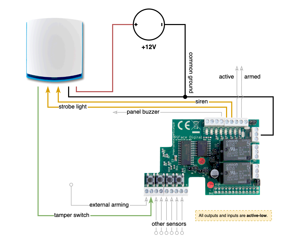
The operation was tested with a discarded [Texecom Odyssey 5E](https://www.texe.com/uk/products/series/external-sounders/premier-series/) siren, whose inputs/outputs should be similar to models from other manufacturers. Just be careful about these things, they're **very loud** (100dB) and can [damage your ears](https://www.chem.purdue.edu/chemsafety/Training/PPETrain/dblevels.htm), especially if you let them go off indoors — I modified mine with an internal switch to easily disconnect it's piezo speaker.
All **inputs** and **outputs** are **active-low**, meaning they're considered to be active when connected to ground. This makes it simpler to interface devices running at different voltages (_simpler_, not necessarily _direct_, read below).
Sensor inputs come in two flavors:
* **normally-closed** (NC), where the sensor outputs a logical low state under normal operation and disconnects when it detects a violation (i.e. becomes _unsealed_). An example of this is a window switch that is usually pressed (closed circuit) while the window is closed.
* **normally-open** (NO), where the sensor only outputs a logical low state when it detects a violation. An example would be a switch under a mat which is pressed when someone steps on it, but is otherwise disconnected (open circuit).
The alarm controller assumes inputs are **normally-open by default** to handle unconnected/unused inputs without tripping itself. But any input can be set as **normally-closed** on initialization.
**Note:** If you think about it for a minute, a normally-closed input is more secure than a normally-open input, because with the latter it isn't possible to detect tampering (actually, real alarm controllers can monitor resistance across the input circuit and that's why you see references to serial and parallel resistors in their manuals, but here we're using just digital inputs).
The PiFace board can drive outputs whose active state is above 5V, but inputs must **always** stay within a 0-5V range to avoid damage. Home sirens and sensors usually run off of a 12V supply and it isn't guaranteed that their logic signals stay within the safe range (they usually do, as they're internally 5V ou 3.3V, but who knows). Test with a voltmeter first to see if you can connect the device directly to the PiFace.
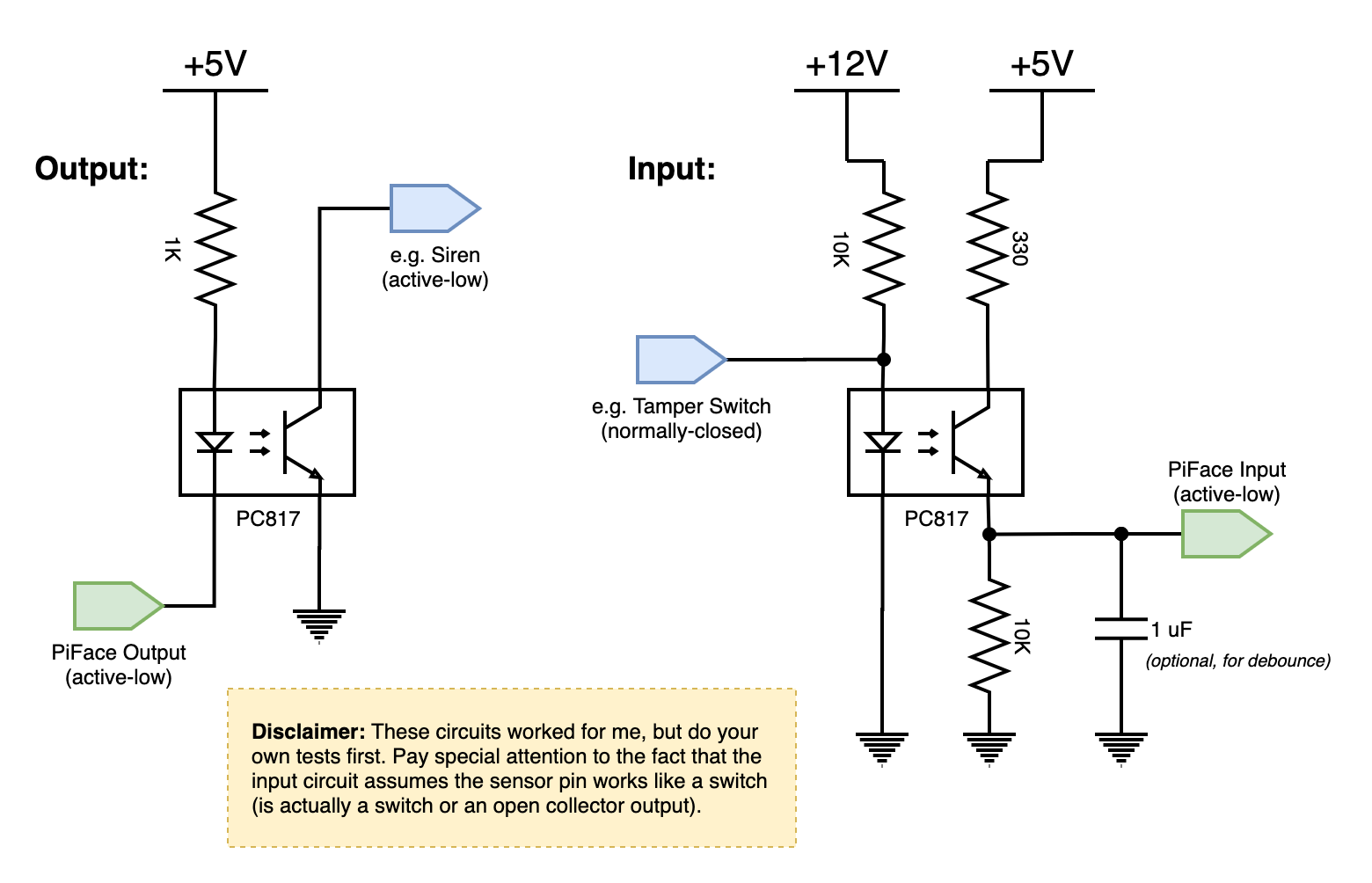
In any case, having sufficient **electrical isolation** on both inputs and outputs is recommended. This is usually accomplished with an optocoupler chip (PC815 or 4N35 are the most common) and a few resistors. The `circuits/isolation.png` diagrams show what I'm using.