https://github.com/chrischrislolo/bunchiez40
A pocket keyboard that makes use of mouse switches to achieve a miniscule size
https://github.com/chrischrislolo/bunchiez40
4x10 keyboard mechanical-keyboard mouse-switches oled oled-display-ssd1306 oled-ssd1306 ortholinear ortholinear-keyboard pocket-board qmk-keyboards rp2040 rp2040-zero
Last synced: 6 months ago
JSON representation
A pocket keyboard that makes use of mouse switches to achieve a miniscule size
- Host: GitHub
- URL: https://github.com/chrischrislolo/bunchiez40
- Owner: ChrisChrisLoLo
- License: gpl-3.0
- Created: 2023-10-08T17:43:41.000Z (almost 3 years ago)
- Default Branch: main
- Last Pushed: 2023-11-28T05:53:59.000Z (over 2 years ago)
- Last Synced: 2025-01-23T02:42:07.497Z (over 1 year ago)
- Topics: 4x10, keyboard, mechanical-keyboard, mouse-switches, oled, oled-display-ssd1306, oled-ssd1306, ortholinear, ortholinear-keyboard, pocket-board, qmk-keyboards, rp2040, rp2040-zero
- Language: OpenSCAD
- Homepage:
- Size: 16.2 MB
- Stars: 36
- Watchers: 3
- Forks: 0
- Open Issues: 0
-
Metadata Files:
- Readme: README.md
- License: LICENSE
Awesome Lists containing this project
README
# bunchiez40
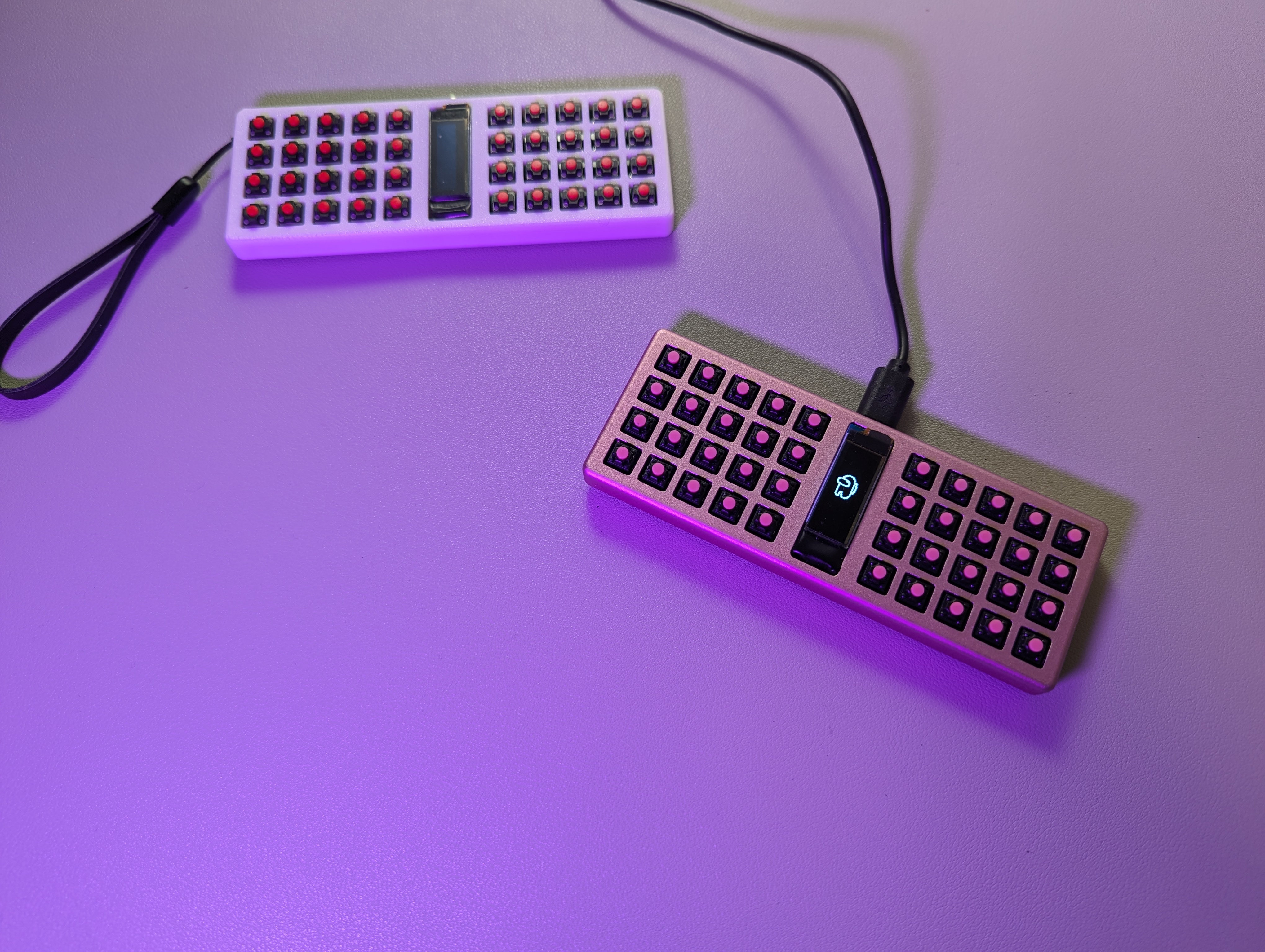
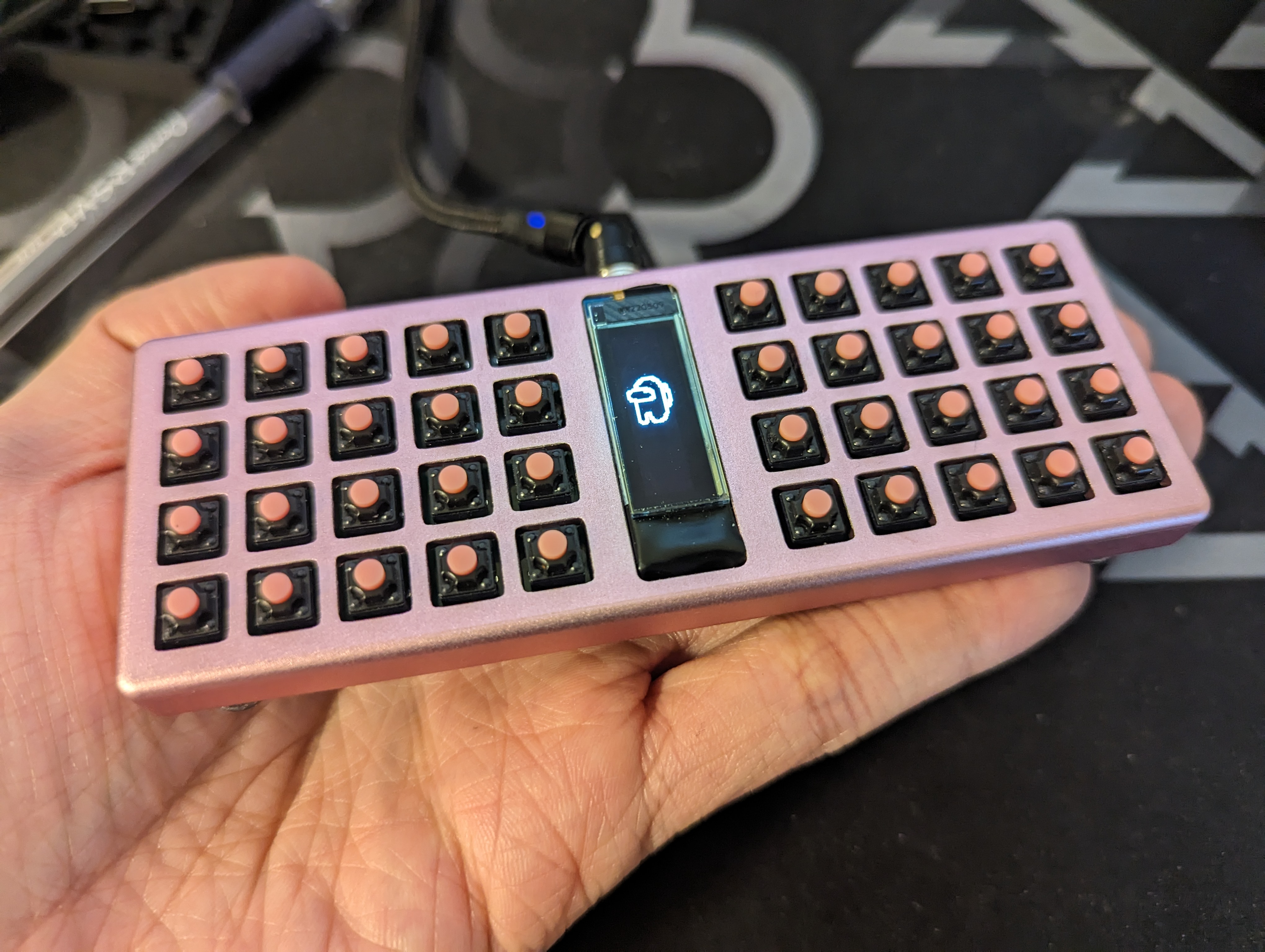
An experimental ultraportable keyboard that uses mouse switches to achieve a compact form factor while still being viable as a daily use keyboard. Board can be hand soldered, and case can be 3D printed or CNC'd.
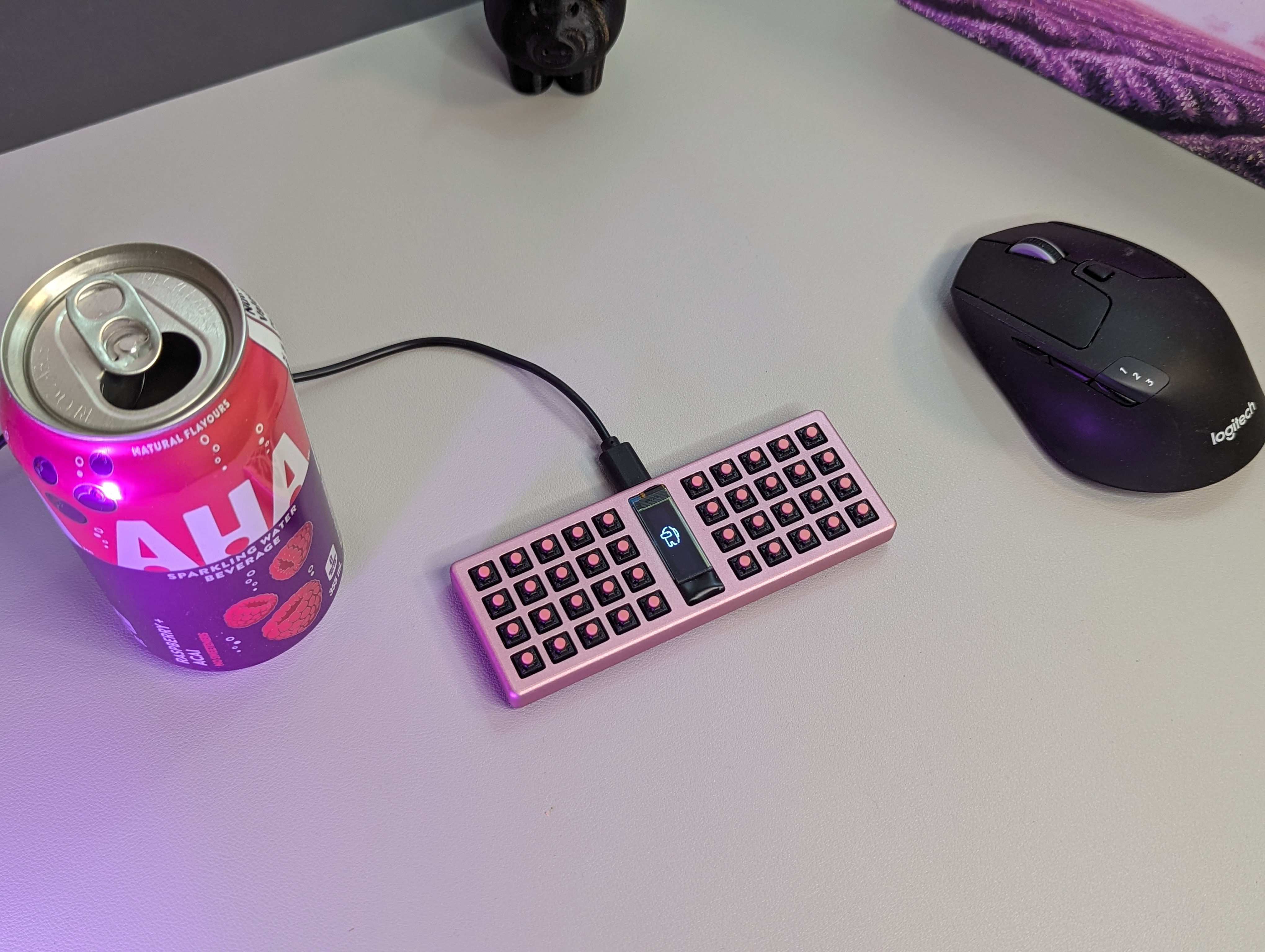
Has science gone too far?
# Status
v0.0 PCBs confirmed to be working! Happy to open up this project for others to play with
# About
I hit the limit as how small I could go with choc switches. I found that kailh mute switches are an ideal small form factor alternative in terms of their size, durability, and actuation force. To make this board more accessible to build at home, it uses a rp2040-zero board that can be soldered on.
More details about my research on mouse switches and experience with the bunchiez40 can be found here: https://chrischrislolo.github.io/orthoLabLogs/bunchiez40-how-i-built-a-keyboard-using-mouse-switches.html
Case files include STLs, STEP files, as well as source OpenSCAD files that can be modified. The OpenSCAD models do not have fillets on them
# Case
The case files can be found in the `case` directory. The particular files you'll want are the `case_holes` file for the top part of the case, and the `case_holes_floor` file for the bottom part. CNC and 3DP works with the top part of the case, and I chose to 3DP my case bottom.
## PCB
You can find the PCB source files in the `pcb` folder. The BOM files can be found in this folder.
## Directory Structure
- `case`
You can find the files you need in this folder to print out a case for the keyboard
- `drafts`
Stores any KLE or intermediate information used in making the case
- `outlines`
Outlines used to create the case and pcb
- `pcb`
Kicad project relating to the project
## BOM
- 1 PCB
- 1 Aluminum CNC upper case or 3DP upper case
- 1 lower case. I 3D printed mine
- 16 3mm M1.6 screws (go for flathead for a flush fit, though other head types should also work)
- 4-8 (ideally 8) 1-2mm bumpons (something like Sj5302 is a good place to start)
- 1 0.91 inch OLED
- 1 rp2040-zero pcb
- 40 Kailh/Huano 7.3mm mute switches (ideally with some spares)
- 40 LL4148 diodes (ideally with some spares)
## Assembly
Build guide coming soon. For now, hopefully the footprints make it clear as to what should go where. Note that the rp2040-zero should be placed in such a way that the MCU is on "top" of the pcb when the assembly is face up, like such.

Once all parts have been assembled, the board can be screwed onto the top of the case with 8 screws.
The firmware should then be flashed onto the board.
The bottom of the board can then be screwed to the case. My recommendation is to put two bumpons on each corner of the bottom of the case, one above the screw and one beside the screw. This helps maximize stability.
## Firmware
QMK Firmware can be found here
https://github.com/ChrisChrisLoLo/vial-qmk/tree/sporewoh/keyboards/sporewoh/bunchiez40