https://github.com/coddingtonbear/bullion
USB & SPI Interface for FS9721-based Multimeters (TP4000ZC)
https://github.com/coddingtonbear/bullion
arduino atmega328pb avr hardware hardware-designs microcontroller multimeter pcb spi spi-interface
Last synced: over 1 year ago
JSON representation
USB & SPI Interface for FS9721-based Multimeters (TP4000ZC)
- Host: GitHub
- URL: https://github.com/coddingtonbear/bullion
- Owner: coddingtonbear
- Created: 2017-01-16T02:20:22.000Z (over 9 years ago)
- Default Branch: master
- Last Pushed: 2017-02-20T07:12:18.000Z (over 9 years ago)
- Last Synced: 2024-10-19T12:38:16.308Z (almost 2 years ago)
- Topics: arduino, atmega328pb, avr, hardware, hardware-designs, microcontroller, multimeter, pcb, spi, spi-interface
- Language: KiCad
- Homepage:
- Size: 116 KB
- Stars: 3
- Watchers: 2
- Forks: 0
- Open Issues: 0
-
Metadata Files:
- Readme: readme.md
Awesome Lists containing this project
README
# USB & SPI Interface for FS9721-based Multimeter (Bullion)
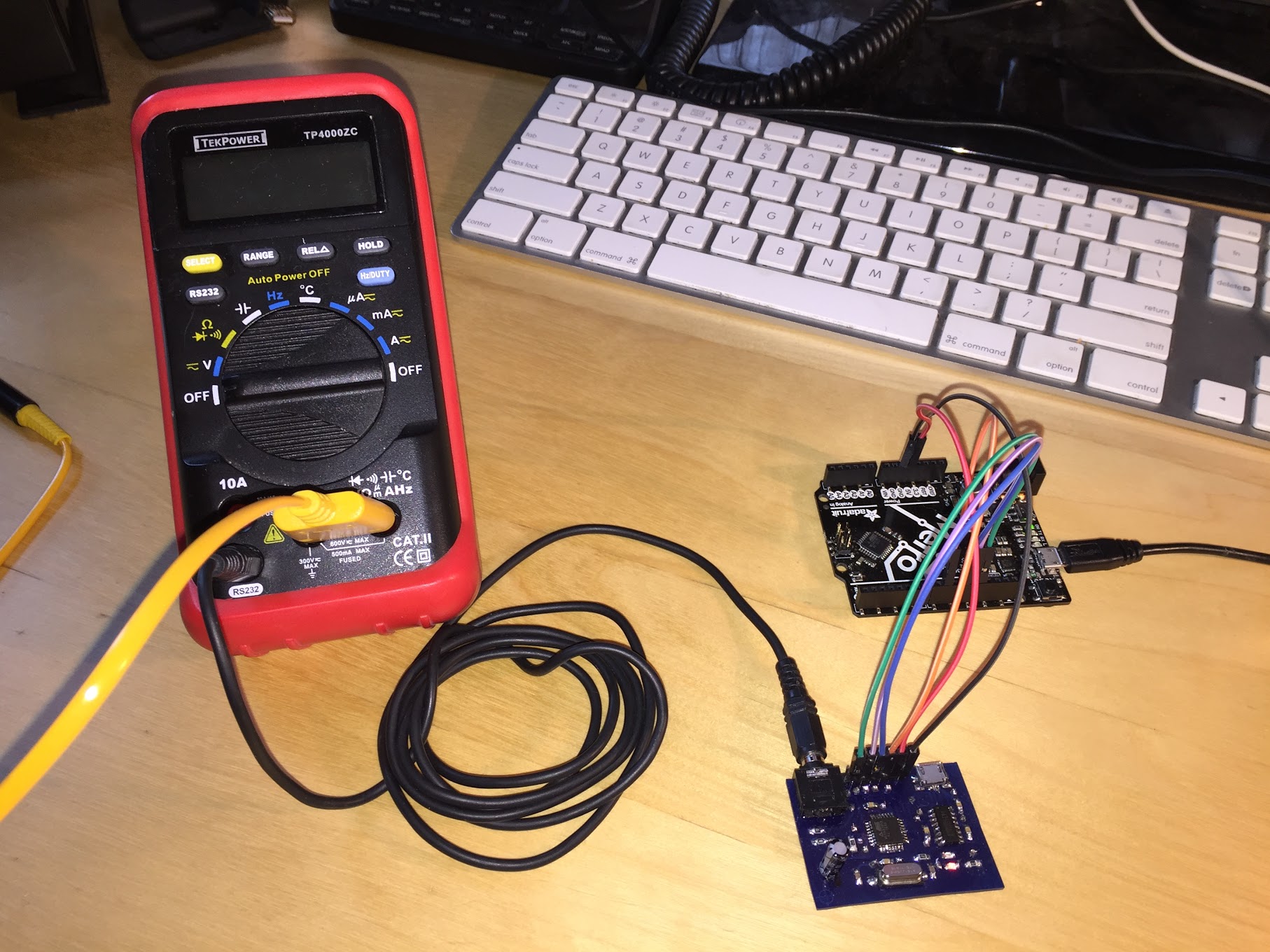
Do you have a cheap Chinese multimeter using the FS9721 chipset and
want to add an easy-to-use USB interface to it? Or, do you have an
arduino project in mind where you might want to collect measurements
from your multimeter? This project can help you do both of those things.
## Compatible Multimeters
Any multimeter using the FS9721 chipset is compatible, but you may have
to adapt the hardware design herein if your multimeter does not have a
3.5mm stereo jack labeled "RS232".
Known-compatible multimeters include:
* **RECOMMENDED** [TekPower TP4000ZC](https://www.amazon.com/Tekpower-TP4000ZC-Interfaced-Multimeter-Computer/dp/B000OPDFLM)
* Also available as the Digitek DT-4000ZC.
* Includes a 3.5mm RS232 port.
* [Mastech V&A 18B](https://www.amazon.com/Manual-Ranging-Digital-Multimeter-Interface/dp/B000LQONYM)
* Does have an external RS232 port, but it is not compatible with the
hardware files you'll find herein. You will have to improvise.
* [UNI-T UT60E](https://www.amazon.com/UNI-T-UT60E-Precise-Light-Weight/dp/B0152OJAWC)
* Does have an external RS232 port, but it is not compatible with the
hardware files you'll find herein. You will have to improvise.
## Interfaces
### USB
* Baud Rate: 2400
When connected to your PC, the device will appear as an additional serial
port (may require installation of a driver for the CH340G USB UART
chip).
By default, the raw output from the Multimeter will be displayed
as new multimeter data is received in a way identical to that of what the
built-in serial port would output were you to connect it directly to your
computer, but you can select a variety of output formats using the below
commands.
#### Commands
Commands are sent in the format `COMMAND=VALUE` followed by a single
newline character.
* Command ``output``:
* Value ``raw`` (*default*): Display raw bytes received from multimeter.
* Value ``value``: Display actual value scaled to base unit.
* Value ``displayed``: Display displayed value. Note that this is
not scaled to the base unit. Use the ``unit`` command below to
determine magnitude.
* Value ``none``: Disable output.
* Command ``units``:
* Value ``0`` (*default*): Do not print unit.
* Value ``1``: Print unit. If the value is not scaled to the base
unit, this may include an SI magnitude prefix ('u', 'n, 'm', 'k', 'M').
**Note**: *Command output is not displayed until you press *
For example; to display units in the format they are displayed on the screen,
you could send the following two commands:
```
output=displayed
units=1
```
and you would, assuming you were measuring a voltage source, receive responses like:
```
1.244 mV
1.239 mV
```
But, if you wanted to output values scaled to their base unit so programs
consuming these values wouldn't need to worry about the SI magnitude, you
could instead send the following commands:
```
output=value
units=1
```
and you'd receive the following values:
```
0.001244 V
0.001239 V
```
You could even turn off unit display if you were not concerned about
identifying what mode the multimeter was in while the returned measurement
was taking place (note, though, that `units=0` is the default state, so
you need not send that command if you have not already enabled unit display):
```
output=value
units=0
```
and then you'd receive very easy-to-parse values:
```
0.001244
0.001239
```
### SPI
Every SPI transaction is a single 8-bit command ID, followed by a
32-bit response.
The following commands are implemented:
* `0x01`: Return multimeter measurement as IEEE 754 floating point value; this
value is scaled to the appropriate base unit for the mode in which the
multimeter is currently operating..
* `0x02`: Return multimeter display as IEEE 754 floating point value.
Note that this value is not scaled to handle displayed SI magnitudes!
* `0x10`: Return current display flags as bits in this order:
* 31:
* 30: Sign
* 29: Low Battery
* 28: Hold
* 27: Rel
* 26: Beep
* 25: Sign (?)
* **24**: RS232
* 23: AUTO
* 22:
* 21:
* 20: M (mega)
* 19: k (kilo)
* 18: m (milli)
* 17: n (nano)
* **16**: µ (micro)
* 15: C2C1 00 (?)
* 14: C2C1 01 (?)
* 13: C2C1 10 (?)
* 12: C2C1 11 (?)
* 11:
* 10: Diode
* 09: DC
* **08**: AC
* 07:
* 06:
* 05: %
* 04: Hz
* 03: V
* 02: A
* 01: F
* 00: Ω
#### SPI Troubleshooting
The device itself operates as an SPI slave, and it's rather difficult to
keep up with fast SPI speeds with just a 12Mhz clock, so if you have unreliable
results, try slowing down your SPI bus speed -- it's not like you're
going to ever be able to get more than a few measurements/second
anyway given that the multimeter itself only measures 2-3x second.
#### Arduino Example
```c
#include
#define MM_PIN 9
void setup() {
digitalWrite(MM_PIN, HIGH);
pinMode(MM_PIN, OUTPUT);
pinMode(MISO, INPUT);
pinMode(MOSI, OUTPUT);
pinMode(SCK, OUTPUT);
SPI.begin();
SPI.beginTransaction(SPISettings(1000, MSBFIRST, SPI_MODE0));
Serial.begin(9600);
}
void loop() {
union {
float measurement;
unsigned char bytes[4];
} floatMeasurement;
digitalWrite(MM_PIN, LOW);
// Let's get the current measurement
SPI.transfer(0x01);
for(uint8_t i = 0; i < 4; i++) {
floatMeasurement.bytes[i] = SPI.transfer(i);
}
Serial.println(floatMeasurement.measurement, 7);
digitalWrite(MM_PIN, HIGH);
delay(500);
// Now let's print the current flags
digitalWrite(MM_PIN, LOW);
SPI.transfer(0x10);
for(uint8_t i = 0; i < 4; i++) {
Serial.println(SPI.transfer(i), BIN);
}
digitalWrite(MM_PIN, HIGH);
delay(3000);
}
```
## Hardware

Check out the `hardware` directory to find Kicad schematics and layout. The
layout you'll find was designed for *homemade* *pcb* *fabrication* (note how
big the vias are and the presence of "transit" vias for working around the
lack of through-hole plating), but it could be sent to your favorite PCB
boardhouse for manufacture if desired.
The following major components are used (see the schematic for details):
* ATMEGA328PB Microcontroller in the QFP package. A normal ATMEGA328P
would work fine, too, but you will have to update a handful of SPI-related
register and interrupt names to remove the extra zero (the -PB version
has two SPI peripherals).
Although the ATMEGA328PB is a little more capable than the ATMEGA328P
these days, they are just a little cheaper; both are around 2.5 USD.
* CH340G USB-to-UART IC: You can buy these from Aliexpress or wherever
for less than 0.50 USD.
* 12Mhz Crystal (SMD HC-49)
* A MicroUSB connector.
* A standard through-hole 3.5mm stereo connector.
Note that the design relies upon the CH340G chip sharing the
microcontroller's clock; you will want to set the `CKOUT=0` fuse
(generally titled "Clock output on PORTB0").
## Future Thoughts
There are lots of things about this project that I'd change if I were to
approach it again; those include:
* Making the primary serial interface I2C instead of SPI.
* I2C provides a lot more flexibility for letting a device take
extra time to perform slow operations via "clock stretching". As
this is currently designed, SPI is used, and the client device must
be able to keep up with the clock speed set by the master or data
will be lost.
* With I2C, you can save a wire or two!
* The downside is that we might have to expose a couple extra pins
since the current header is used for both programming and the serial
interface. If I2C is added, either two additional header pins will
need to be added, or maybe a multiplexer chip allowing two header
pins to be shared individually between two different microcontroller
pins.
* Orient the microcontroller at a 45˚ angle. This should make routing a
little less chaotic.
* Add reverse current protection! Not having such protection was a little
bit of an embarassing oversight.
* Use either a MicroUSB breakout board or a MiniUSB connector instead of
the existing MicroUSB connector. Soldering that tiny connector onto
a homemade PCB is very difficult -- the pin pitch of those connectors
is 0.65mm; just a smidge below what my current process is able to
resolve (~0.75mm) without needing to use a sharp knife to separate
traces.
* Perhaps place devices on both sides of the board to save space? It's
not clear to me whether that would be worth it, but it could make the
board a lot smaller.