https://github.com/danielmartensson/stm32-plc
STM32 microcontroller with lots of periferials such as ADC, differential ADC, Input Capture, PWM, USB, Encoder, DAC, Digital Input, RTC, CAN-bus + Alarm etc.
https://github.com/danielmartensson/stm32-plc
c can-bus embedded-systems stm32 usb
Last synced: about 1 year ago
JSON representation
STM32 microcontroller with lots of periferials such as ADC, differential ADC, Input Capture, PWM, USB, Encoder, DAC, Digital Input, RTC, CAN-bus + Alarm etc.
- Host: GitHub
- URL: https://github.com/danielmartensson/stm32-plc
- Owner: DanielMartensson
- License: mit
- Created: 2021-08-18T14:25:17.000Z (almost 5 years ago)
- Default Branch: main
- Last Pushed: 2024-02-09T12:38:10.000Z (over 2 years ago)
- Last Synced: 2024-02-09T13:56:45.287Z (over 2 years ago)
- Topics: c, can-bus, embedded-systems, stm32, usb
- Language: C
- Homepage:
- Size: 59.5 MB
- Stars: 70
- Watchers: 4
- Forks: 30
- Open Issues: 0
-
Metadata Files:
- Readme: README.md
- License: LICENSE
Awesome Lists containing this project
README
# STM32 PLC
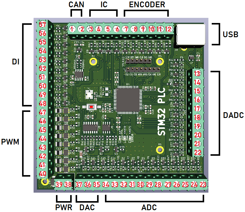
This project is a PCB bord that has the following measurement and control input/output:
* 12 x ADC at 16-bit resolution for 0-20mA input with programmable gain
* 5 x Differential ADC at 16-bit for 0-20mA input with programmable gain
* 3 x DAC at 12-bit with 0-20mA output
* 8 x PWM for 0-2.2A with N-channel MOSFET
* 10 x Digital Input
* 1 x CAN-bus channel
* 4 x Input Capture for 0 kHz to 10kHz
* 3 x Encoder for -32768 to 32767 pulses
* 1 x USB port for connecting with [OpenSourceLogger](https://github.com/DanielMartensson/OpenSourceLogger) and [GoobySoft](https://github.com/DanielMartensson/GoobySoft)
* 1 x SPI with 3 chip select for ILI9341 LCD with touch
* 1 x ST-Link V2 connection
* 1 x RTC clock with two alarms A(date) and B(week day) and a battery holder so the RTC remembers the date and time
## Protection
* All ADC, Digital Input, Differential ADC, Input Capture and Encoder are high voltage protected with PTC(fall current 30mA) fuse + 3.6v zener diode.
* All PWM and DAC are high voltage protected with N-channel MOSFET and PNP-transistor and OP-amp.
* The CAN-bus channel is high voltage peak protected for 3000V under a short time with a TVS-diode. The CAN-bus transmitter itself can hold against -14V to +14V, but the TVS-diode has a limit around 6V.
## Documentation
The documentation for the pin map can be found in the `Documentation` folder. Also all the article numbers for each component can be found in at the `DAC ADC PWM IO.sch` file in the `PCB` folder. Just double click on a PCB symbol and see the `Mouser Electronics` article number of the electrical component.
## Calibration
Yes, it's possible to set the calibration to each input in this project. You need to have the ILI9341 touch LCD with SPI bus. Open the `STM32 PLC Pinouts.pdf` and see the connection for the LCD. You can also set the PWM frequency and analog input gain for the ADC and Differential ADC at 16-bit.
## SAE J1939
The STM32 PLC has internal SAE J1939 protocol. Made from [Open-SAE-J1939](https://github.com/DanielMartensson/Open-SAE-J1939) repository.
## OpenSourceLogger
This is a QT C++ software that you can connect to your STM32 PLC board via the USB and then you can send signals from OpenSourceLogger and recieve signals.
OpenSourceLogger is a very easy to use logging and controlling software and it stores data at a SQL server.
## GoobySoft
This is a ImGui C++ project that do the same as OpenSourceLogger, but it's much better and have more features. The reason why I moved away from QT C++ to ImGui C++ is because
it's much easier to write a GUI application in C++ by using ImGui instead of QT. With QT, you are stuck with object oriented programming. Everything is a class.
But for ImGui, you can choose which type of lever you want to code, I prefer C-style C++ code with a small dose of object oriented programming (if needed).
Consider that I will work on GoobySoft instead of OpenSourceLogger.
## Program
The STM32 PLC has a lot of functions you can select by touching the LCD.
* A:Show measurement and time
* B:Set analog gain
* C:Set PWM frequencies
* D:Set analog input calibration
* E:Set pulses per encoder revolution
* F:Set date and time and alarm
* G:Do a PGN request
* H:Show ECU addresses
* I:Commanded address
* J:Show this ECU DM1 codes
* K:Show other ECU DM1 codes
* L:Show this ECU DM2 codes
* M:Show other ECU DM2 codes
* N:Show this ECU name
* O:Show other ECU name
* P:Show this ECU identifications
* Q:Show other ECU identifications
* R:SAE J1939 Auxiliary valve command
* S:Analog in to PWM
* T:Analog in to analog out
* U:About STM32 PLC
## How to build this STM32 PLC
1. Download this repository
2. Download & Install KiCad
3. Open the `PCB` folder and open the `.pro` file with KiCAD and greate a `gerber` file of your own choice
4. Go to your PCB manufacturer and give them the `gerber` file and let them produce the board for you
5. Order the eletrical components from `Mouser Electronics`
6. Once you have the eletrical components and your PCB board, it's time to solder them.
7. Once the PCB board is finished, then install STM32CubeIDE
8. Open the `Code` project and import the `.ioc` project file using STM32CubeIDE
9. Flash the board with the `C` code by using ST-Link V2 connection
10. Connect the ILI9431 touch LCD and then you are done!
## Software used
* KiCAD: 6.0.7
* STM32CubeIDE 1.10.1
## Status of the project
It's done. I don't plan to update this project. Everything is working and it will remain that way.