Ecosyste.ms: Awesome
An open API service indexing awesome lists of open source software.
https://github.com/esprfid/esp-rfid-board
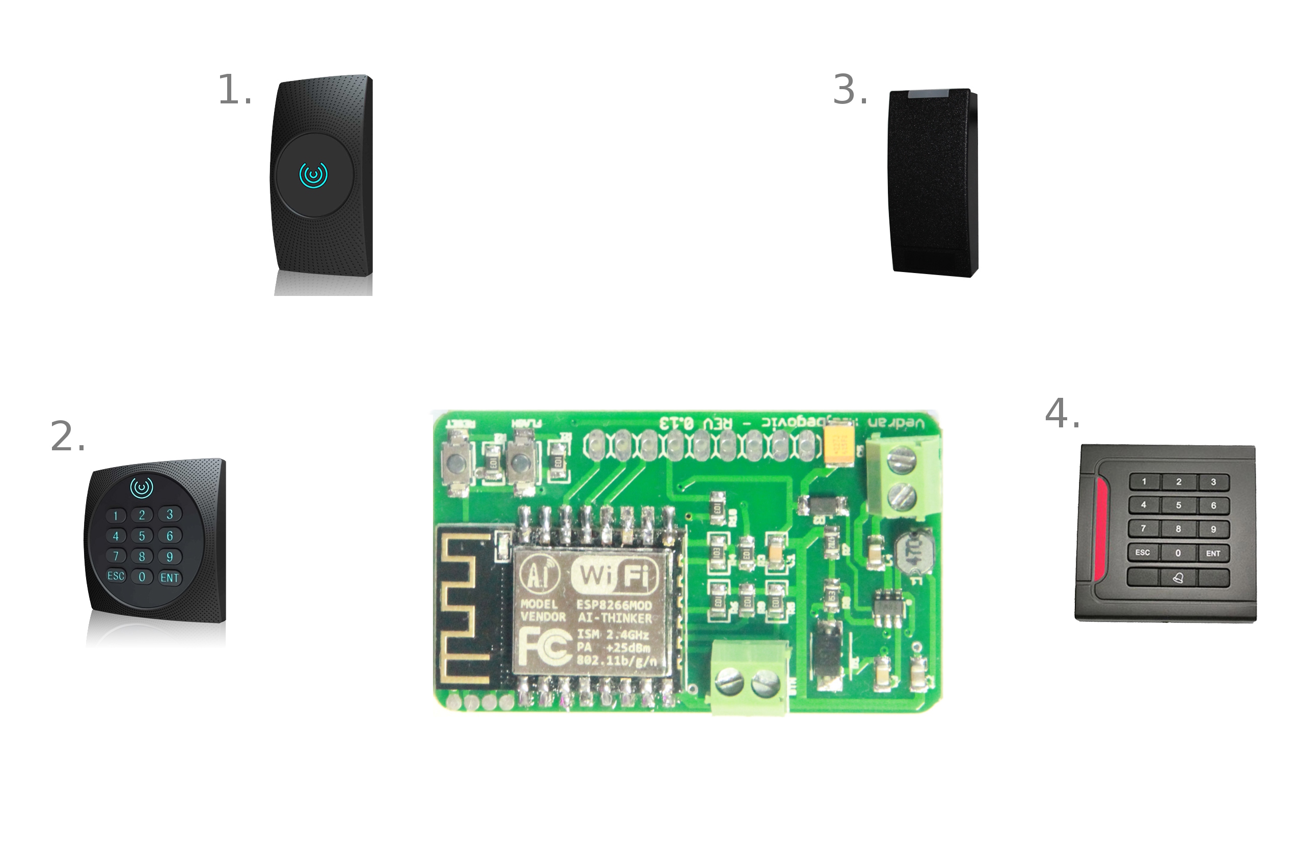
ESP8266/ESP12 breakout board which handles 12V input and accept all wires from popular wiegand readers.
https://github.com/esprfid/esp-rfid-board
esp wiegand-reader
Last synced: 25 days ago
JSON representation
ESP8266/ESP12 breakout board which handles 12V input and accept all wires from popular wiegand readers.
- Host: GitHub
- URL: https://github.com/esprfid/esp-rfid-board
- Owner: esprfid
- Created: 2018-03-16T20:25:55.000Z (almost 7 years ago)
- Default Branch: master
- Last Pushed: 2018-09-25T12:41:41.000Z (about 6 years ago)
- Last Synced: 2024-02-23T23:36:36.629Z (10 months ago)
- Topics: esp, wiegand-reader
- Size: 3.92 MB
- Stars: 11
- Watchers: 3
- Forks: 4
- Open Issues: 0
-
Metadata Files:
- Readme: README.md
Awesome Lists containing this project
README
# ESP12 / ESP12F / ESP12E / ESP12S Wiegand rfid board
Small ESP12F breakout board, custom built for Wiegand RFID readers.
### You can get this board from my Tindie shop:

WARNING: Although it’s rated for more than 12V, i strongly suggest to use maximum of 12V input!
Check the image for explanation of how to hook up the reader
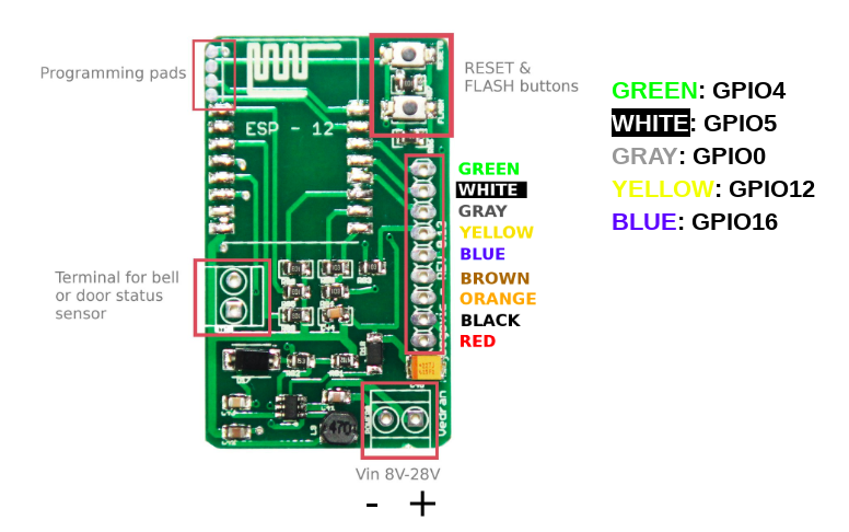
** There is a resistor on the way from ESP to buzzer due to strange behaviour of busser that ditn't react to HIGN/LOW except if there is a resitor on the way from ESP to Wiegand reader.
Custom pads
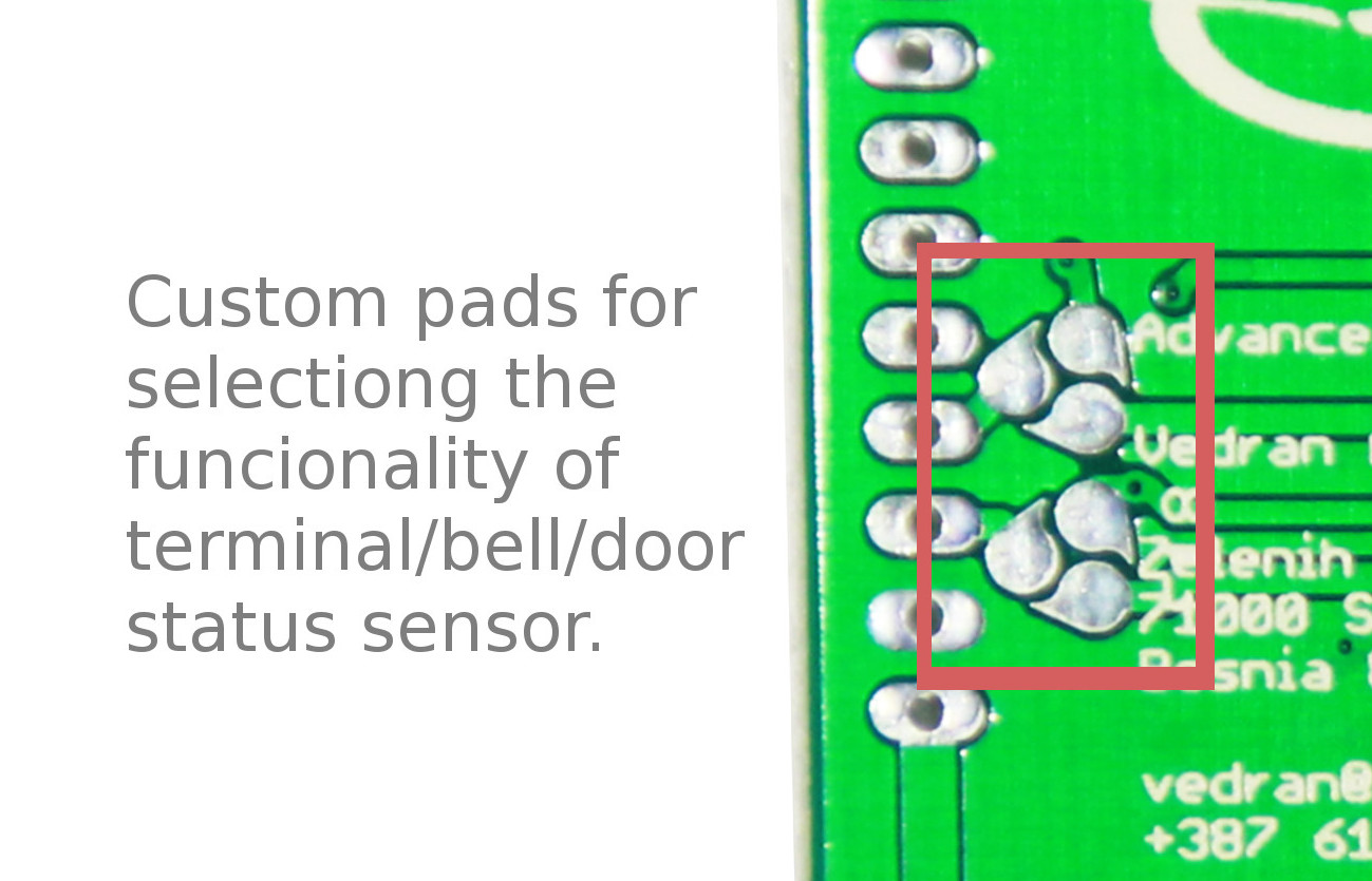
** New board has marked pads
**Option 1:**
Solder 2 and 1 on both pads results in passing “Ring” tactile switch/button to ESP8266 pin GPIO14
**Option 2:**
Solder 3 and 2 on both pads results in passing “Ring” switch to a terminal on another side of board.
**Option 3:**
Solder 1 and 3 on both pads results in passing terminal pins to ESP8266 GPIO14, planned so that you can hook door status magnet sensor. In this case, you can’t use “Ring” button in Option 1. or 2.

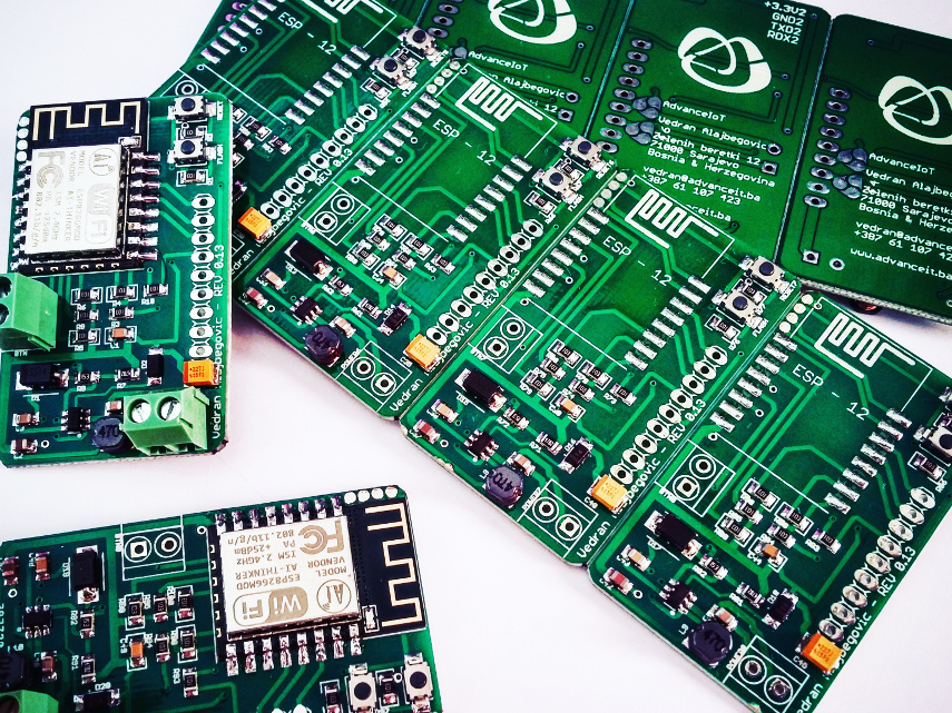
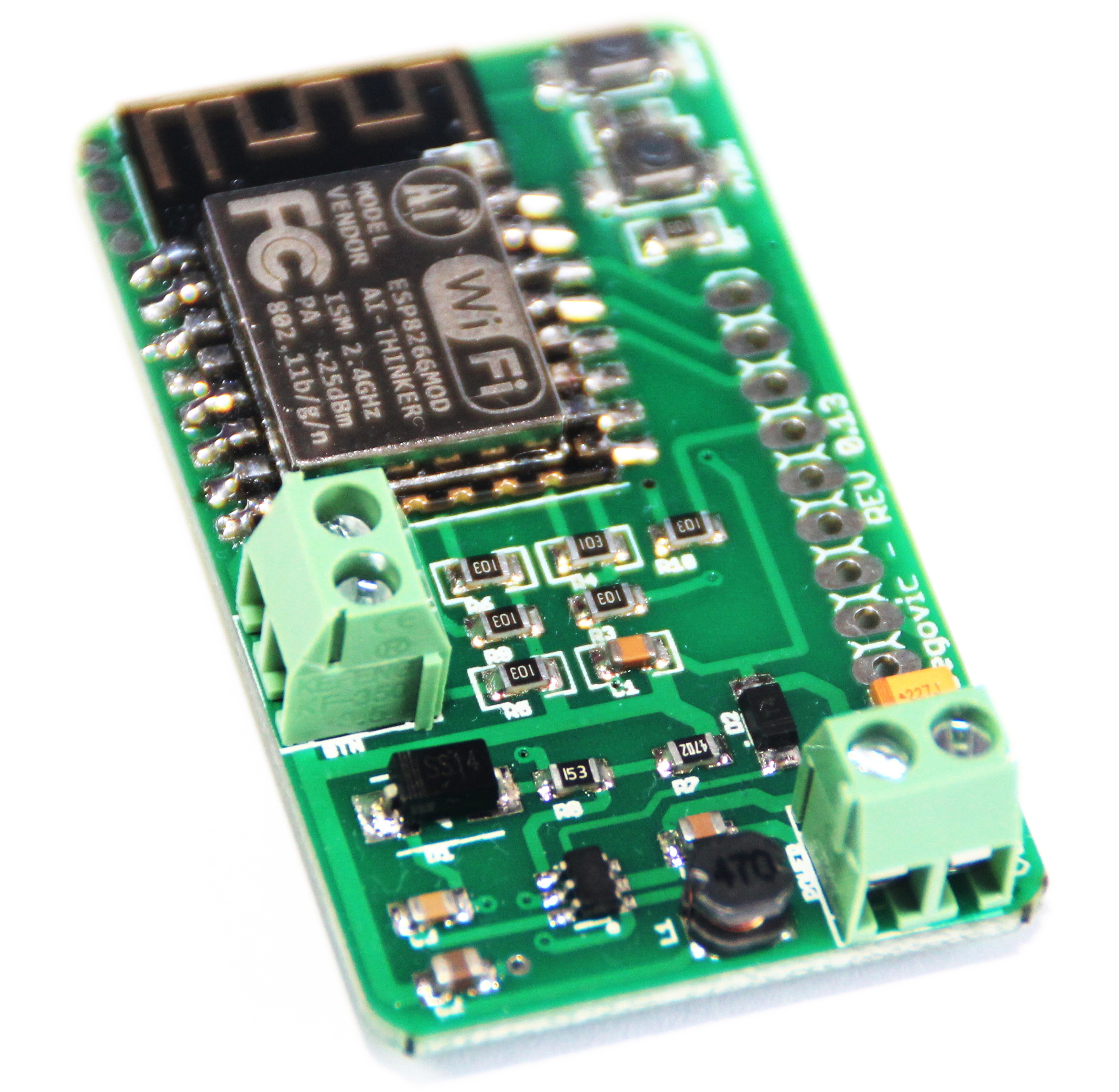
* BOM has some mistakes, contact me if you need some help.