https://github.com/formix/retroz
An S80 Single Board Retro Computer
https://github.com/formix/retroz
board bom electronics pcb-layout retrocomputing sio z80
Last synced: 3 months ago
JSON representation
An S80 Single Board Retro Computer
- Host: GitHub
- URL: https://github.com/formix/retroz
- Owner: formix
- License: apache-2.0
- Created: 2018-09-22T15:32:54.000Z (over 7 years ago)
- Default Branch: master
- Last Pushed: 2020-03-30T11:36:27.000Z (about 6 years ago)
- Last Synced: 2025-12-19T20:24:09.947Z (6 months ago)
- Topics: board, bom, electronics, pcb-layout, retrocomputing, sio, z80
- Language: VBA
- Homepage:
- Size: 3.61 MB
- Stars: 20
- Watchers: 2
- Forks: 4
- Open Issues: 0
-
Metadata Files:
- Readme: README.md
- License: LICENSE
Awesome Lists containing this project
README
# RetroZ SBC S80
A minimalist single board Z80 retro computer based on the S80 design
specifications.
This board is developped using the S80 physical specifications. The
specifications are not currently available online but I plan to fix that in a
future revision.
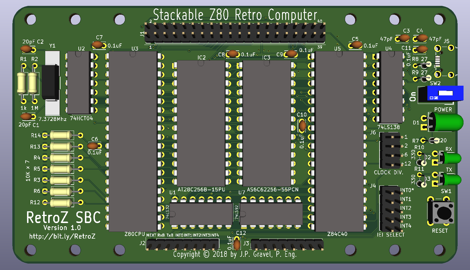
*Front of the board*
[Back of the board](https://raw.githubusercontent.com/formix/RetroZ/master/Documents/RetroZ-SBC-Back.png)
You can find the board schematic as a PDF [here](https://github.com/formix/RetroZ/blob/master/Documents/RetroZ-SBC.pdf).
## BOM
You can download the BOM [here](https://github.com/formix/RetroZ/blob/master/Projects/RetroZ-SBC/RetroZ-SBC-BOM.ods?raw=true). It is an Open Document Worksheet file and you should be able to open it with Open/Libre Office or MS Excel. If you have issue, contact me.
| Comp. | Mouser# | Digikey# | Mfr# | Qty | Description |
|----------------------------|----------|---------------|--------------------|-----|------------------------------------|
| C1,C2 | | | C317C200J5G5TA | 2 | 20pf Capacitor |
| C3,C4 | | | FG28C0G1H470JNT06 | 2 | 47pF Capacitor |
| C5,C6,C7,C8,C9,C10,C11,C12 | | | C322C104K5R5TA7301 | 8 | 0,1uF Capacitors |
| D1 | | | 151051VS04000 | 1 | Green Led 5mm |
| D2,D3 | | | 151031SS06000 | 2 | Red Led 3mm Round, FwdV 2.2 |
| IC1 | | | ADM803TAKSZ-REEL7 | 1 | Power-on Reset chip |
| IC2 | | | AT28C256-15PU | 1 | EEPROM 256kbit 28-Pin PDIP |
| IC2,IC3 | | | 4828-6004-CP | 2 | CONN IC DIP SOCKET 28POS TIN |
| IC3 | | | AS6C62256-55PCN | 1 | IC SRAM 256K PARALLEL 28DIP |
| J1 | 485-2223 | 1528-1385-ND | 2223 | 1 | Adafruit stacking header 2x20 |
| J2,J3 | 485-85 | 1528-1074-ND | 85 | 1 | STACKING HEADER ARDUINO SHIELD |
| J4 | | | PRPC005DAAN-RC | 1 | 5x2 Pin Connector |
| J4,J6 | | | QPC02SXGN-RC | 2 | 1x2 Shunt connector |
| J5 | | | 629105150521 | 1 | USB Microb B SMT Connector |
| J6 | | | PRPC004DAAN-RC | 1 | 4x2 Pin Connector |
| R1 | | | RNF14FTD1M00 | 1 | 1M Ohm Resistor |
| R10,R11 | | | RNF14FTD332R | 2 | 332 Ohm resistor |
| R2 | | | RNF14FTD1K00 | 1 | 1k Ohm Resistor |
| R3,R4,R5,R6,R12,R13,R14 | | | RNF14FTD10K0 | 7 | 10k Ohm Resistor |
| R7 | | | RNF14FTD221R | 1 | 221 Ohm Resistor |
| R8,R9 | | | RNF14FTD27R4 | 2 | 27 Ohm Resistors |
| SW2 | | | BD01 | 1 | DIP Switch x1 |
| U1 | | | 74LS32 | 1 | Quand OR |
| U2 | | | 74HCT04 | 1 | Hex Inverter Schmidt Trigger |
| U3 | | | Z84C0008PEG | 1 | Z80 CPU |
| U3,U5 | | | 4840-6004-CP | 1 | 40 pin (2 x 20) DIP socket 15,24mm |
| U4 | | | SN74LS138N | 1 | 3 to 8 Decoder/Demux |
| U5 | | | Z84C4208PEG | 1 | Z80 SIO/2 |
| U6 | | | FT230XS-U | 1 | UART to USB |
| U7 | | | 74LS92 | 1 | Dodecade counter (div. By 12) |
| Y1 | | | ECS-73-20-5PX-TR | 1 | 7,3728 MHz Crystal |
## Development Note
### 2019-01-15
The review phase is done! I just sent the board to production. I should get the
finished board next week.
### 2019-01-26
I recieved my boards (10 boards!) yesterday. I just finished creating the BOM
and sorted through my parts to order what is missing. I expect to recieve my
order in the coming week. I'll work on the NASCOM Basic once I got the
computer assembled. Stay tuned!
### 2019-08-03
It's been a while since I updated that README file but as you can see,
I'm committing regularily on the project. Simply put, I'm too busy playing
with my working RetroZ SBC computer to update the front documentation. It is
time to fix that, continue reading to get the full update.
## What's Inside?
The RetroZ-SBC computer is a 8MHz Z80 CPU clocked at 7.3728 MHz. It supports
up to 32kB of ROM and 32kB of RAM. An SIO/2 chip is connected to the USB
Micro B socket using an FTDI serial converter. Rx and Tx leds let you know
when the computer communicates over USB. The whole computer is powered through
the same USB port and a power-on reset monitor resets the computer at startup.
A Reset button allows warm computer restart. An On/Off DIP switch controls the
power state of the computer and a power led indicator let you know that the
beast is powered. All the Z80 processor pins are available through the 40 pins
stacking header plus some other on the User Port A. User Port B stacking
header is fully available (8 pins) for child boards future projects.
## The Connection
The USB to serial conversion is made possible thanks to an FTDI chip
[behind the board](https://raw.githubusercontent.com/formix/RetroZ/master/Documents/RetroZ-SBC-Back.png)
and is clocked at 115200 bauds by default. This speed can be changed
programmatically through the Z84C40 (Zilog SIO/2) registers. On a Windows
machine the device can be accessed using **COM5**. For a
Mac/Linux box it is **/dev/ttyUSB0**. Hardware flow control CTS/RTS is fully
wired so feel free to flood the console with whatever you get, it should
handle it.
## Technical Reference
### Power and commnunication over USB
Using a single USB Micro-B wire, it is possible to power-up and communicate
with the computer. There is a DIP switch to set the computer on or off and a
power indicator led indicates when the computer is powered on. There is also
a power line monitor chip (IC1) that pull the /RESET line LOW for 240 ms
after power on.
### Serial Communication
Serial communication is achieved using a Z84C42 SIO/2 chip. The serial port A
is connected to the USB jack through an FTDI UART to USB 2.0 converter. Rx
and Tx leds indicate when communication occurs on that port. The serial port
B is connected back into the User Port A (J2) PIN 2 (RxB) and Pin 3 (TxB) for
slave cards serial communications.
**The serial port A clock** is directly tied to the clock and can be changed
programmatically from the SIO/2 registers. In the NASCOM Basic provided, it is
set to 115200 by default.
**The serial port B clock** The default speed is set to 115200 bauds as well.
Again, that speed can be programmatically changed. The serial clock on port B
goes through a dodecade counter and can be further adjusted using the
`Clock div.` (J6) jumper that offers another set of 1,2,6 and 12 dividers.
That gives a wide variety of standard baud rates down to 9600 bauds.
### Onboard memory control
The PIN 1 of the User Port A is pulled low with a 2k resistor. This is the
on-board memory enable input pin (/ME). To disable onboard memory, an
expansion card can set that pin HIGH. This would be the case with a memory
expansion board. It can be hardwired to 5V to disable the onboard memory
completely or it can be tied to some logic to leverage the on-board memory as
needed.
### Interrupt Chaining
The RetroZ SBC design allows chaining interrupts of up to 4 slave boards. The
onboard SIO/2 IEO pin is hardwired to the User Port A INT0 (PIN 4). Its
Interrupt Enable In pin can be tied to any of the other INT pins using the
IEI Select jumper (J4). Selecting the first position of that jumper (INT0)
sets the on-board SIO/2 as the Master. On slave boards, the Interrupt Enable
In will have 6 positions. Also, a 4 positions IEO jumper header should be
provided to select the right User Port A IEO position (pins 5-8). More on
that on the slave board design document.
**WARNING** User Port A pins 4-8 (interrupts) are not protected. If you
connect a daughter board without checking jumper settings first, you could
short an IO pin on your stack and damage a chip! Looking into a solution to
that in a future revision.