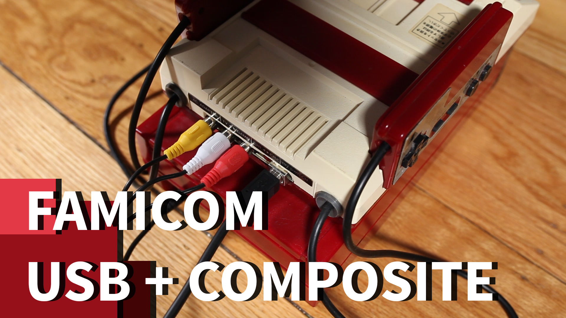
https://github.com/hakkslab/FamicomPowerBoard
A USB/composite power board replacement for the Famicom
https://github.com/hakkslab/FamicomPowerBoard
Last synced: 5 months ago
JSON representation
A USB/composite power board replacement for the Famicom
- Host: GitHub
- URL: https://github.com/hakkslab/FamicomPowerBoard
- Owner: hakkslab
- Created: 2018-09-19T02:12:33.000Z (over 7 years ago)
- Default Branch: master
- Last Pushed: 2018-10-06T17:58:57.000Z (over 7 years ago)
- Last Synced: 2024-04-15T00:14:53.417Z (almost 2 years ago)
- Size: 39.1 KB
- Stars: 23
- Watchers: 7
- Forks: 5
- Open Issues: 0
-
Metadata Files:
- Readme: README.md
Awesome Lists containing this project
- awesome-portablizing - FamicomPowerBoard - Open source power board replacement for Famicom which adds AV RCA jacks (Nintendo / NES)
README
[](https://www.youtube.com/watch?v=6UGa3aDpMOE)
# Famicom USB + Composite Power Board Replacement
In this repository you'll find the schematic and PCB layout for the Famicom powerboard replacement as shown in [this episode of Hakk's Lab](https://www.youtube.com/watch?v=6UGa3aDpMOE). You'll need [Design Spark PCB](https://www.rs-online.com/designspark/pcb-download-and-installation) to open the project files. Exported gerber files can be found in the `gerber/` directory.
## Parts List
Below are the parts used in this layout with suggestions for potential improvements or changes.
- 1 [3 RCA female AV cocentric socket](http://a.co/d/7VnQlFh)
- 1 USB connector of your choice. For this layout, I used a [female USB type-B connector](http://a.co/d/i00tf1e)
- 3 150 ohm resistor. Alternatively, two of these could be replaced with a 300 ohm resistor. I didn't have any 300s, so I seriesed up a couple 150s to get the correct resistance
- 1 110 ohm resistor
- 1 PNP transistor
- 1 1uF electrolytic capacitor
- 1 220uF electrolytic capacitor
- 1 red LED. Honestly, it could be any color, but be sure you use the correct resistor for whatever you actually use. I think red is appropriate in this case because 80s technology and it matches the colors of the Famicom.