https://github.com/initdc/challenger_rp2040_wifi
https://github.com/initdc/challenger_rp2040_wifi
Last synced: 4 days ago
JSON representation
- Host: GitHub
- URL: https://github.com/initdc/challenger_rp2040_wifi
- Owner: initdc
- License: other
- Created: 2023-02-08T12:30:15.000Z (about 3 years ago)
- Default Branch: main
- Last Pushed: 2023-02-08T12:30:28.000Z (about 3 years ago)
- Last Synced: 2025-08-01T05:55:27.208Z (7 months ago)
- Homepage: https://gitlab.com/invectorlabs/hw/challenger_rp2040_wifi.git
- Size: 137 KB
- Stars: 2
- Watchers: 1
- Forks: 0
- Open Issues: 0
-
Metadata Files:
- Readme: README.md
- License: LICENSE.md
Awesome Lists containing this project
README
# The Challenger RP2040 WiFi

## Challenger RP2040 WiFi information
The Challenger RP2040 WiFi board is an Arduino/Circuitpython compatible Adafruit Feather format micro controller board packed with loads of functionality for your projects that requires a WiFi connection.
The main controller of this board is the Raspberry Pi Pico (RP2040) with 8MByte of FLASH memory and 264KByte of SRAM. The RP2040 MCU is built around the dual 32-bit ARM® Cortex™-M0 CPU's running at up to 133 MHz. It has numerous digital peripherals and interfaces such as high speed SPI and QSPI for interfacing to external flash and a full speed USB device for data transfer and power supply for battery recharging.
## Challenger RP2040 WiFi Key features
- Dual ARM® Cortex M0 running at up to 133MHz
- 8 MB Flash, 264 KB RAM
- 2.4GHz WiFi modem
- UART, SPI, TWI, I2S
- PWM
- 12-bit ADC
- USB 2.0
## The board
### WiFi solution
The WiFi modem is an ESP8285 WiFi chip. For those of you that is unfamiliar with this device, it is basically an ESP8266 device with an integrated 1MByte of flash memory. This allows us to have an AT command interpreter inside this chip that the main controller can talk to and connect to you local WiFi network. The communications channel between the two devices is an unused UART on the main controller and the standard UART on the ESP8285. As simple as it can be.
### Power
There is an onboard low power LDO that runs the onboard electronic devices. The board also comes with a connector for external LiPo batteries as well as a LiPo charger circuit that.
### Other stuff
It also has the Challenger standard USB type C connector with ajoining LED's. A red LED for the charging circuit indicating when the attached battery is being charged and a green user programmable LED. In addition to this there is also a blue LED that can be used for signaling RF activity, or anything else really, to the user. The UF2 boot loader uses this LED to indicate that it is waiting for your code to be uploaded. Additionally there is also a user programmable tactile switch that can be used for user input. This button is also used by the boot loader to enter DFU mode.
Anf of course, there is a reset switch. You can not survive without the reset switch =)
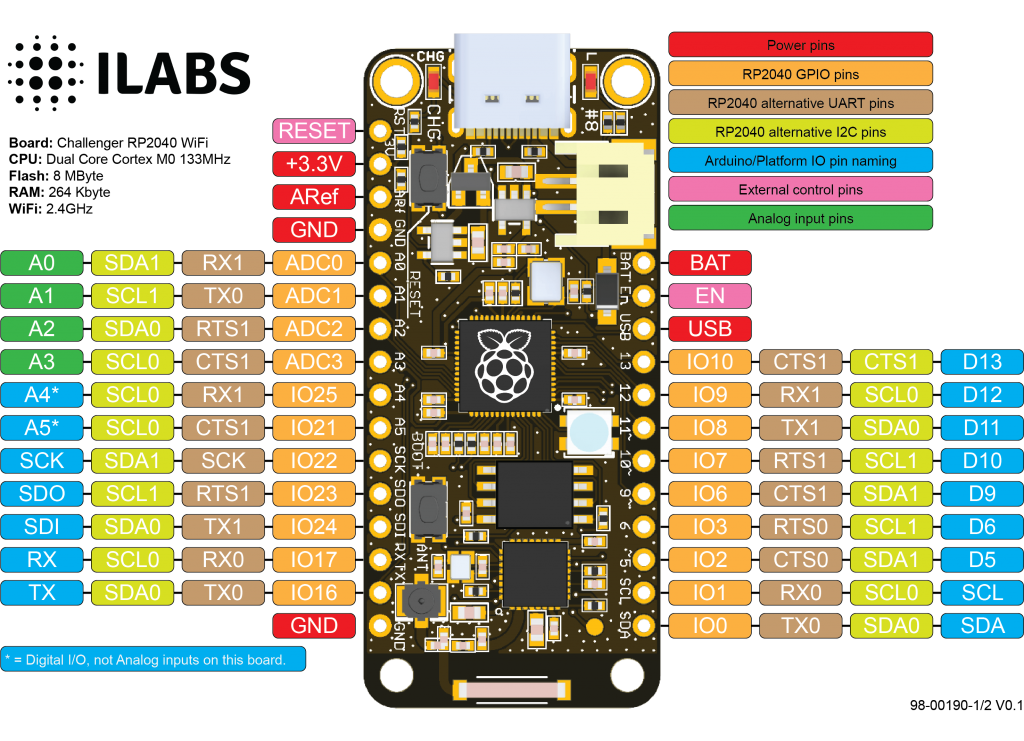
### Pinout
### Software support
The board is supported by both the Arduino environment as well as Circuitpython from Adafruit.
## License
This design covered by the CERN Open Hardware Licence v1.2 and a copy of this license is also available in this repo.
## iLabs

### About us
Invector Labs is a small Swedish engineering company that designs and build electronic devices for hobbyists as well as small and medium sized businesses.
For more information about this board you can visit the product page at our [website](https://ilabs.se/product/challenger-2040-wifi/)
Questions about this product can be addressed to .
/* EOF */