https://github.com/kill-ux/deep-in-net
Networking fundamentals project using Cisco Packet Tracer — covers devices, (DHCP, DNS, HTTP/S, FTP), OSI model layers, routing, and multi-subnet architectures across 8 progressive exercises.
https://github.com/kill-ux/deep-in-net
cisco cisco-packet-tracer dhcp dns ftp http https layers osi protocols subnet
Last synced: 29 days ago
JSON representation
Networking fundamentals project using Cisco Packet Tracer — covers devices, (DHCP, DNS, HTTP/S, FTP), OSI model layers, routing, and multi-subnet architectures across 8 progressive exercises.
- Host: GitHub
- URL: https://github.com/kill-ux/deep-in-net
- Owner: kill-ux
- Created: 2026-04-07T11:55:09.000Z (4 months ago)
- Default Branch: main
- Last Pushed: 2026-06-25T09:32:18.000Z (30 days ago)
- Last Synced: 2026-06-25T11:05:10.893Z (30 days ago)
- Topics: cisco, cisco-packet-tracer, dhcp, dns, ftp, http, https, layers, osi, protocols, subnet
- Homepage: https://github.com/kill-ux/deep-in-net
- Size: 742 KB
- Stars: 0
- Watchers: 0
- Forks: 0
- Open Issues: 0
-
Metadata Files:
- Readme: README.md
Awesome Lists containing this project
README
# deep-in-net 🌐
A hands-on networking project built with **Cisco Packet Tracer**, covering
foundational concepts in network design, device configuration, protocol
behavior, and the OSI model — from simple peer-to-peer connections to
multi-subnet routed architectures.

---
## Table of Contents
1. [OSI Model](#osi-model)
2. [Cables](#cables)
3. [Devices](#devices)
4. [IP Addressing & Subnetting](#ip-addressing--subnetting)
5. [Protocols](#protocols)
6. [Routing](#routing)
7. [Exercises](#exercises)
8. [Bonus](#bonus)
9. [File Structure](#file-structure)
---
## OSI Model
The OSI model describes the 7 layers of network communication.
Every protocol and device maps to a specific layer.
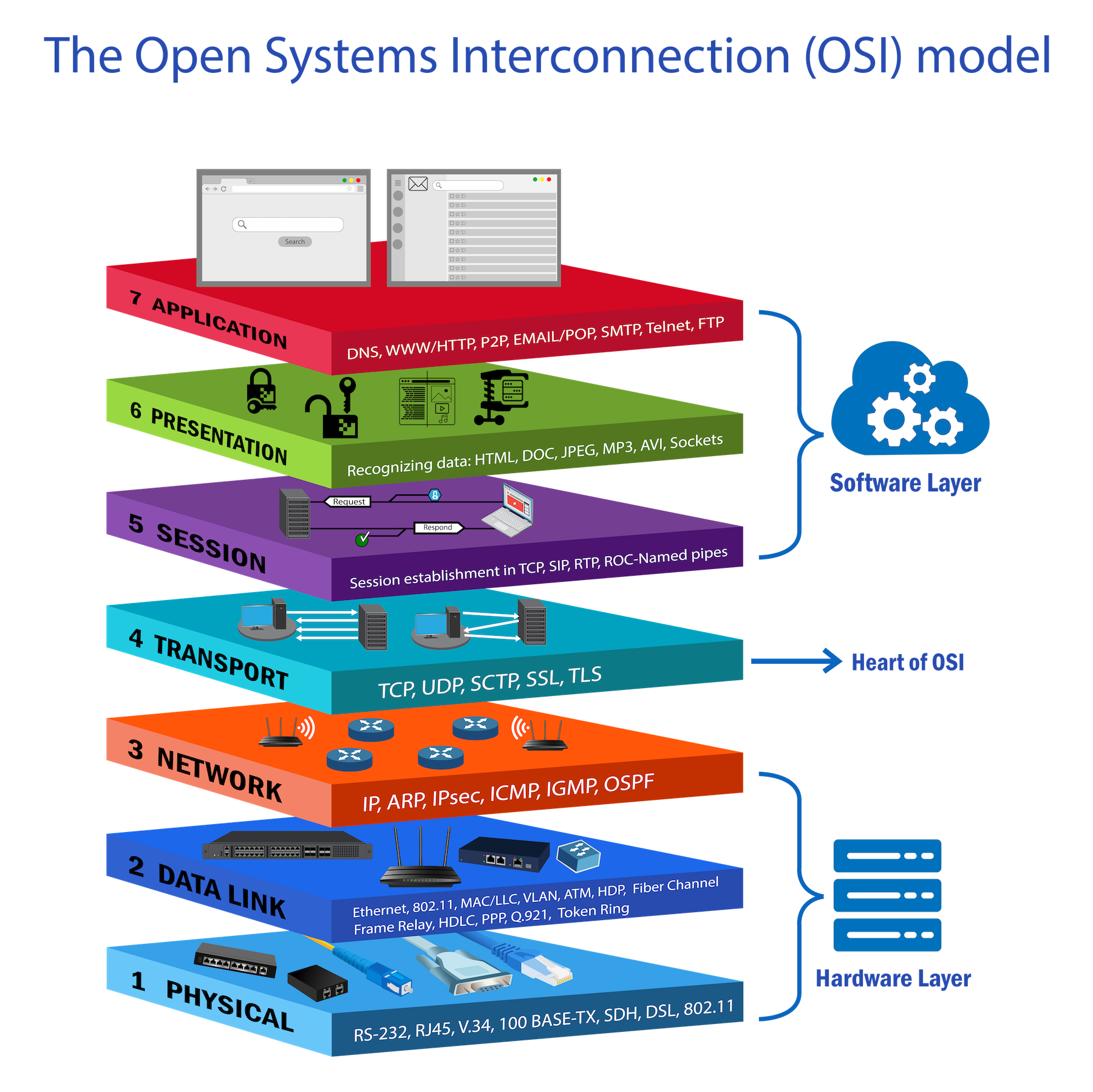
```
Layer 7 — Application → HTTP, HTTPS, FTP, DNS, DHCP
Layer 6 — Presentation → TLS/SSL encryption
Layer 5 — Session → session management
Layer 4 — Transport → TCP, UDP (ports)
Layer 3 — Network → IP, ICMP, ARP, Router
Layer 2 — Data Link → MAC addresses, Switch, Frames
Layer 1 — Physical → Cables, Hub, Bits
```
| Device | OSI Layer | Works with |
|--------|-----------|---------------|
| Hub | Layer 1 | Bits |
| Switch | Layer 2 | MAC addresses |
| Router | Layer 3 | IP addresses |
---
## Cables
### RJ-45 — the 4 pins that matter
```
Pin 1 — TX+ Pin 2 — TX− (Transmit)
Pin 3 — RX+ Pin 6 — RX− (Receive)
```
TX on one side must connect to RX on the other.
### Port types
| Type | Device | Transmits on | Receives on |
| ----- | -------------------- | ------------ | ----------- |
| MDI | PC, Laptop , Router | 1 & 2 | 3 & 6 |
| MDI-X | Switch, Hub | 3 & 6 | 1 & 2 |
### The rule
```
MDI ←→ MDI-X → Straight-through (opposite types, swap in device)
MDI ←→ MDI → Crossover (same type, cable does the swap)
MDI-X ←→ MDI-X → Crossover (same type, cable does the swap)
```
### Straight-through
```
PC (MDI) Switch (MDI-X)
TX+ pin1 ────────────────── pin1 RX+
TX− pin2 ────────────────── pin2 RX−
RX+ pin3 ────────────────── pin3 TX+
RX− pin6 ────────────────── pin6 TX−
```
### Crossover pinout
```
PC A (MDI) PC B (MDI)
TX+ pin1 ──────╮─────────── pin3 RX+
TX− pin2 ────╮─╰─────────── pin6 RX−
RX+ pin3 ────╰───────────── pin1 TX+
RX− pin6 ────────────────── pin2 TX−
```
### Reference
| Connection | Cable |
| --------------- | ---------------------- |
| PC → Switch | Straight-through |
| PC → Router | Crossover |
| PC → PC | Crossover |
| Switch → Switch | Crossover |
| Switch → Router | Straight-through |
| Modern devices | Either (Auto-MDI/MDIX) |
---
## Devices
### Hub — Layer 1
Dumb repeater — any signal received is copied to ALL other ports.
```
PC-A sends to PC-C → hub floods to PC-B, PC-C, PC-D
PC-B and PC-D must discard it → waste + collisions
```
- Half-duplex: send OR receive, never both
- One shared collision domain for all devices
- Uses CSMA/CD to handle collisions
### Switch — Layer 2
Learns MAC addresses and forwards frames only to the correct port.
```
PC-A sends to PC-C → switch sends ONLY to PC-C
PC-B and PC-D hear nothing → efficient + private
```
- Full-duplex: send AND receive simultaneously
- Each port is its own collision domain
- Builds MAC address table from source MACs of incoming frames
### Router — Layer 3
Connects different networks and forwards packets based on destination IP.
```
Switch → connects devices INSIDE one network
Router → connects DIFFERENT networks together
```
Packet forwarding:
```
1. Packet arrives with destination IP
2. Router checks routing table (longest prefix match)
3. Decrements TTL by 1
4. Rewrites MAC address (src=router, dst=next hop)
5. Forwards out correct interface
```
IP address never changes hop to hop. MAC address changes at every hop.
---
## IP Addressing & Subnetting
### Subnet formula
```
Block size = 2^(32 - prefix)
Usable IPs = block size - 2
Network = floor(IP ÷ block size) × block size
Broadcast = network + block size - 1
```
### Example — 111.111.111.83/29
```
Step 1: 32 - 29 = 3 host bits → 2³ = 8 (block size)
Step 2: 83 ÷ 8 = 10.375
Step 3: drop decimal → 10
Step 4: 10 × 8 = 80 ← network address
Step 5: 80 + 8 - 1 = 87 ← broadcast
111.111.111.80 → network (reserved)
111.111.111.81 → host ✓
111.111.111.82 → host ✓
111.111.111.83 → host ✓ ← your IP
111.111.111.84 → host ✓
111.111.111.85 → host ✓
111.111.111.86 → host ✓
111.111.111.87 → broadcast (reserved)
```
### Common subnet reference
```
Prefix Mask Block Usable
/24 255.255.255.0 256 254
/26 255.255.255.192 64 62
/27 255.255.255.224 32 30
/28 255.255.255.240 16 14
/29 255.255.255.248 8 6
/30 255.255.255.252 4 2
/32 255.255.255.255 1 1
```
---
## Protocols
### Protocol & Port Reference
| Protocol | Port | Transport | Layer | Purpose |
|----------|-------|-----------|-------|----------------------------|
| DHCP | 67/68 | UDP | L7 | Automatic IP assignment |
| DNS | 53 | UDP/TCP | L7 | Name → IP resolution |
| HTTP | 80 | TCP | L7 | Web (unencrypted) |
| HTTPS | 443 | TCP | L7 | Web (TLS encrypted) |
| FTP | 20/21 | TCP | L7 | File transfer |
| RIP | 520 | UDP | L7 | Dynamic routing |
| ARP | — | — | L2/3 | IP → MAC resolution |
| ICMP | — | IP proto | L3 | Ping, traceroute, errors |
| OSPF | — | IP 89 | L3 | Dynamic routing enterprise |
### TCP vs UDP
```
TCP → reliable, ordered, connection-oriented
confirms every packet → HTTP, HTTPS, FTP
UDP → fast, no guarantee, connectionless
fire and forget → DHCP, DNS, RIP
```
### ARP
Converts IP → MAC before any frame can be sent.
```
PC checks ARP cache → not found
PC broadcasts: "Who has 192.168.1.20?" (FF:FF:FF:FF:FF:FF)
Target replies: "I do — AA:BB:CC:DD:EE:FF" (unicast)
PC stores in ARP cache → sends frame
```
```
Same subnet → ARP for destination IP
Other subnet → ARP for default gateway IP
```
### ICMP
Used for testing and error reporting. Not for data transfer.
```
Type 0 Echo Reply → ping response
Type 8 Echo Request → ping request
Type 3 Destination Unreachable → cannot reach host
Type 11 Time Exceeded → TTL = 0 (traceroute)
```
### DHCP
DORA handshake:
```
D — DISCOVER broadcast "I need an IP" src=0.0.0.0
O — OFFER reply "I offer 192.168.1.10"
R — REQUEST broadcast "I accept 192.168.1.10"
A — ACKNOWLEDGE reply "It's yours"
```
Assigns: IP, subnet mask, gateway, DNS server, lease time.
### DNS
Record types:
```
A domain → IPv4 main address record
CNAME alias → name www → domain (alias)
MX domain → mail email routing
PTR IP → domain reverse lookup
TXT domain → text SPF, DKIM, verification
```
In Exercise 3:
```
deep-in-net.local → 192.168.1.99 A record
deep-in-net.com → deep-in-net.local CNAME record
```
### FTP
```
Port 21 → control (commands)
Port 20 → data (file transfer)
Permissions: R read W write D delete N rename L list
RWDNL = full access
```
### HTTP & HTTPS
```
HTTP → plain text port 80 insecure
HTTPS → TLS encrypted port 443 secure
```
TLS handshake:
```
1. Client Hello → supported versions + ciphers
2. Server Hello → chosen cipher + certificate
3. Verify cert → check CA, domain, expiry
4. Key exchange → encrypted pre-master secret
5. Session key → both sides derive same key independently
6. Finished → tunnel confirmed, data flows
```
### RIP
```
Type: Distance Vector | Metric: hop count | Max: 15 | Port: UDP 520
router rip
version 2
network 192.168.1.0
no auto-summary
```
### OSPF
```
Type: Link State | Metric: bandwidth cost | Max: unlimited | Port: IP 89
router ospf 1
network 192.168.1.0 0.0.0.255 area 0
```
Note: OSPF uses wildcard masks — inverse of subnet mask.
255.255.255.0 → 0.0.0.255 | 255.255.255.252 → 0.0.0.3
---
## Routing
### Static vs Dynamic
```
Static → admin adds routes manually, simple, no overhead
does not adapt if link fails
Dynamic → routers share routes automatically (RIP or OSPF)
adapts when topology changes
```
### Default Gateway
IP of the router interface on the device's local subnet.
Used to forward packets destined outside the local network.
### Serial — DCE and DTE
```
DCE → provides clock signal (ISP side in real life)
DTE → receives clock (customer router)
```
In Packet Tracer: clock icon = DCE → must configure clock rate.
```
clock rate 64000 = 64 Kbps
no shutdown = turn interface ON (all interfaces OFF by default)
```
---
## Exercises
### Exercise 1 — Direct PC Communication
**Topology:** 3 pairs of PCs connected directly.
**Cable:** Crossover — PC to PC = MDI to MDI = same type → cable must swap TX↔RX.
**IP addresses from topology:**
```
Pair 1 — /24 subnet:
PC1: 192.168.1.4/24 mask 255.255.255.0
PC0: 192.168.1.3/24 mask 255.255.255.0
Pair 2 — /29 subnet (block of 8):
PC3: 192.168.13.83/29 mask 255.255.255.248
PC2: 192.168.13.81/29 mask 255.255.255.248
Block check: 83 ÷ 8 = 10 → 10×8=80 (network), 87 (broadcast)
Both .81 and .83 are in range 80–87 ✓
Pair 3 — /29 subnet:
PC5: 129.168.13.249/29 mask 255.255.255.248
PC4: 192.168.13.254/29 mask 255.255.255.248
```
**Steps:**
```
1. Place two PCs
2. Connect with crossover cable
3. Click PC → Desktop → IP Configuration → Static
4. Enter IP and mask (no gateway needed — direct connection)
5. Repeat for each pair
```
**Verify:**
```
PC0> ping 192.168.1.4 → reply ✓
PC2> ping 192.168.13.83 → reply ✓
```
---
### Exercise 2 — Switch vs Hub
**Topology:** 5 PCs on 2960-24TT switch | 5 PCs on hub.
**IP addresses:**
```
Switch group — /29 subnet (block 8):
S-PC1 to S-PC5: 193.168.1.1/29 to 193.168.1.5/29
mask: 255.255.255.248
Hub group — /27 subnet (block 32):
H-PC1 to H-PC5: 193.168.1.193/27 to 193.168.1.197/27
mask: 255.255.255.224
```
**Steps:**
```
1. Place 2960-24TT switch and a hub separately
2. Connect each PC with straight-through cable (PC=MDI → Switch/Hub=MDI-X)
3. Assign static IPs to each PC (same subnet per group)
4. No gateway needed — all same subnet
```
**Behavior difference:**
```
Switch → unicast to correct port only
Hub → floods to ALL ports, others discard
```
**Verify:**
```
S-PC1> ping 193.168.1.5 → reply ✓
H-PC1> ping 193.168.1.197 → reply ✓
```
---
### Exercise 3 — Network Services
**Topology:** 4 servers + 6 PCs on one 2960-24TT switch.
**Server static IPs:**
| Server | IP | Mask | Service |
|-------------|---------------|---------------|----------------------|
| HTTP SERVER | 192.168.1.99 | 255.255.255.0 | HTTPS only |
| FTP SERVER | 192.168.1.100 | 255.255.255.0 | File transfer |
| DNS SERVER | 192.168.1.101 | 255.255.255.0 | Name resolution |
| DHCP SERVER | 192.168.1.102 | 255.255.255.0 | IP assignment |
**PCs:** receive IPs automatically from DHCP (range starts at 192.168.1.7/24).
**Steps:**
1 — Set static IPs on all 4 servers:
```
Click server → Desktop → IP Configuration → Static
IP: as table above | Mask: 255.255.255.0 | DNS: 192.168.1.101
```
2 — Configure DHCP server:
```
Click DHCP server → Services → DHCP → ON
Default gateway: 192.168.1.1
DNS server: 192.168.1.101
Start IP: 192.168.1.7
Subnet mask: 255.255.255.0
```
3 — Configure HTTPS server:
```
Click HTTP server → Services → HTTP → OFF
Click HTTP server → Services → HTTPS → ON
Edit index.html → add hello message
```
4 — Configure DNS server:
```
Click DNS server → Services → DNS → ON
Add: deep-in-net.local A 192.168.1.99
Add: deep-in-net.com CNAME deep-in-net.local
```
5 — Configure FTP server:
```
Click FTP server → Services → FTP → ON
Add user: deepinnet / deepinnet / RWDNL
```
6 — Set PCs to DHCP:
```
Click PC → Desktop → IP Configuration → DHCP
PC receives IP automatically
```
**Verify:**
```
PC> ping 192.168.1.99 → server reachable ✓
PC> browser → https://deep-in-net.com → hello page ✓
PC> ftp 192.168.1.100 → login deepinnet → access ✓
```
---
### Exercise 4 — Router Basics
**Topology:** PC0 ── Router1 (1841) ── PC1
**IP addresses:**
```
PC0: 192.168.1.2/30 gateway 192.168.1.1
PC1: 192.168.2.2/30 gateway 192.168.2.1
Router1: Fa0/0 = 192.168.1.1/30 (toward PC0)
Fa0/1 = 192.168.2.1/30 (toward PC1)
```
**Steps:**
```
Router1> enable
Router1# configure terminal
interface FastEthernet0/0
ip address 192.168.1.1 255.255.255.252
no shutdown
interface FastEthernet0/1
ip address 192.168.2.1 255.255.255.252
no shutdown
end
write memory
```
Set on PCs:
```
PC0: IP 192.168.1.2 mask 255.255.255.252 gateway 192.168.1.1
PC1: IP 192.168.2.2 mask 255.255.255.252 gateway 192.168.2.1
```
**Verify:**
```
PC0> ping 192.168.2.2 → reply ✓
PC1> ping 192.168.1.2 → reply ✓
```
---
### Exercise 5 — Two Subnets via Router
**Topology:** Switch0 ── Router0 (2911) ── Switch1
**IP addresses:**
```
Subnet 1 — /29 (block 8):
PC0–PC4: 192.168.1.2 to 192.168.1.6/29
Router0 Gi0/0: 192.168.1.1/29 mask 255.255.255.248
Subnet 2 — /27 (block 32):
PC5–PC9: 192.168.1.194 to 192.168.1.198/27
Router0 Gi0/1: 192.168.1.193/27 mask 255.255.255.224
```
**Steps:**
```
Router0> enable
Router0# configure terminal
interface GigabitEthernet0/0
ip address 192.168.1.1 255.255.255.248
no shutdown
interface GigabitEthernet0/1
ip address 192.168.1.193 255.255.255.224
no shutdown
end
write memory
```
Set on PCs:
```
Subnet1 PCs: mask 255.255.255.248 gateway 192.168.1.1
Subnet2 PCs: mask 255.255.255.224 gateway 192.168.1.193
```
**Verify:**
```
PC0> ping 192.168.1.194 → cross-subnet ✓
PC5> ping 192.168.1.2 → cross-subnet ✓
```
---
### Exercise 6 — Static Routing
**Topology:** PC0 ── Router0 ──serial── Router1 ── PC2
**IP addresses:**
```
PC0: 192.168.1.2/24 gateway 192.168.1.1
PC2: 192.168.2.2/24 gateway 192.168.2.1
Router0: Fa0/0 = 192.168.1.1/24 (toward PC0)
Se0/0/0 = 10.10.0.1/30 (toward Router1) DCE
Router1: Se0/0/0 = 10.10.0.2/30 (toward Router0) DTE
Fa0/0 = 192.168.2.1/24 (toward PC2)
```
**Steps:**
Router0 (DCE — clock icon):
```
enable
configure terminal
interface FastEthernet0/0
ip address 192.168.1.1 255.255.255.0
no shutdown
interface Serial0/0/0
ip address 10.10.0.1 255.255.255.252
clock rate 64000
no shutdown
ip route 192.168.2.0 255.255.255.0 10.10.0.2
end
write memory
```
Router1 (DTE):
```
enable
configure terminal
interface FastEthernet0/0
ip address 192.168.2.1 255.255.255.0
no shutdown
interface Serial0/0/0
ip address 10.10.0.2 255.255.255.252
no shutdown
ip route 192.168.1.0 255.255.255.0 10.10.0.1
end
write memory
```
**Verify:**
```
PC0> ping 192.168.2.2 → reply ✓
PC2> ping 192.168.1.2 → reply ✓
Router0# show ip route → S 192.168.2.0 via 10.10.0.2 ✓
```
---
### Exercise 7 — Multi-device Routing
**Topology:** PC0–PC4 on Switch0 ── Router0 ──serial── Router2 ── Switch1 ── Laptop0, PC5–PC7
**IP addresses:**
```
Subnet 1: 192.168.1.0/24
PC0–PC4: 192.168.1.2–192.168.1.6/24
Router0 Fa0/0: 192.168.1.1/24
Serial: 10.10.0.0/30
Router0 Se0/0/0: 10.10.0.1/30 (DCE)
Router2 Se0/0/0: 10.10.0.2/30 (DTE)
Subnet 2: 192.168.2.0/24
Laptop0, PC5–PC7: 192.168.2.2–192.168.2.5/24
Router2 Fa0/0: 192.168.2.1/24
```
**Steps:**
Router0 (DCE):
```
interface FastEthernet0/0
ip address 192.168.1.1 255.255.255.0
no shutdown
interface Serial0/0/0
ip address 10.10.0.1 255.255.255.252
clock rate 64000
no shutdown
ip route 192.168.2.0 255.255.255.0 10.10.0.2
```
Router2 (DTE):
```
interface Serial0/0/0
ip address 10.10.0.2 255.255.255.252
no shutdown
interface FastEthernet0/0
ip address 192.168.2.1 255.255.255.0
no shutdown
ip route 192.168.1.0 255.255.255.0 10.10.0.1
```
**Verify:**
```
PC0> ping 192.168.2.2 → reply ✓
Laptop0> ping 192.168.1.2 → reply ✓
```
---
### Exercise 8 — Three-Subnet Full Mesh
**Topology:** 3 routers, 3 switches, 3 subnets, 2 DHCP servers.
**IP addresses:**
```
Subnet 1: 192.168.1.0/26 (block 64, usable .1–.62)
PC0–PC4 + DHCP1 on Switch0
Router0 Gi0/0: 192.168.1.1/26 mask 255.255.255.192
Serial link 1 (Router0 ↔ Router2): 10.10.0.0/30
Router0 Se0/0/0: 10.10.0.1/30 (DCE)
Router2 Se0/0/0: 10.10.0.2/30
Serial link 2 (Router2 ↔ Router1): 10.10.1.0/30
Router2 Se0/0/1: 10.10.1.2/30
Router1 Se0/0/0: 10.10.1.1/30
Subnet 2: 192.168.2.0/24
DHCP2, Laptop0, PC5–PC7 on Switch3
Router1 Fa0/0: 192.168.2.1/24 mask 255.255.255.0
Subnet 3: 192.168.3.160/28 (block 16, usable .161–.174)
PC8, PC9, PC710, DHCP2(1) on Switch2
Router2 Fa0/0: 192.168.3.161/28 mask 255.255.255.240
```
**Steps:**
Router0:
```
interface GigabitEthernet0/0
ip address 192.168.1.1 255.255.255.192
no shutdown
interface Serial0/0/0
ip address 10.10.0.1 255.255.255.252
clock rate 64000
no shutdown
ip route 192.168.2.0 255.255.255.0 10.10.0.2
ip route 192.168.3.160 255.255.255.240 10.10.0.2
```
Router2:
```
interface Serial0/0/0
ip address 10.10.0.2 255.255.255.252
no shutdown
interface Serial0/0/1
ip address 10.10.1.2 255.255.255.252
no shutdown
interface FastEthernet0/0
ip address 192.168.3.161 255.255.255.240
no shutdown
ip route 192.168.1.0 255.255.255.192 10.10.0.1
ip route 192.168.2.0 255.255.255.0 10.10.1.1
```
Router1:
```
interface Serial0/0/0
ip address 10.10.1.1 255.255.255.252
no shutdown
interface FastEthernet0/0
ip address 192.168.2.1 255.255.255.0
no shutdown
ip route 192.168.1.0 255.255.255.192 10.10.1.2
ip route 192.168.3.160 255.255.255.240 10.10.1.2
```
**Verify:**
```
PC0> ping 192.168.2.2 → subnet1 → subnet2 ✓
PC0> ping 192.168.3.162 → subnet1 → subnet3 ✓
PC5> ping 192.168.3.162 → subnet2 → subnet3 ✓
Router0# show ip route → all 3 subnets present ✓
```
---
## File Structure
```
deep-in-net/
├── ex01.pkt direct PC pairs (crossover)
├── ex02.pkt switch vs hub
├── ex03.pkt DHCP, DNS, HTTPS, FTP servers
├── ex04.pkt basic router
├── ex05.pkt two subnets via router
├── ex06.pkt static routing two routers
├── ex07.pkt multi-device routing
├── ex08.pkt three-subnet full mesh
└── README.md this file
```
---
> "Networking plays a critical role in various IT specialties,
> and is particularly essential for cloud and DevOps engineering.
> Be curious and never stop searching!"