https://github.com/martonmiklos/robomow_rm_510_mainboard_schematic
Reverse engineered schematic parts for the Robomow RM-510 lawn mower
https://github.com/martonmiklos/robomow_rm_510_mainboard_schematic
eagle eagle-cad lawnmower reverse-engineering reverseengineering rm-200 rm-510 robomow schematic schematics
Last synced: 7 months ago
JSON representation
Reverse engineered schematic parts for the Robomow RM-510 lawn mower
- Host: GitHub
- URL: https://github.com/martonmiklos/robomow_rm_510_mainboard_schematic
- Owner: martonmiklos
- Created: 2020-09-12T20:38:44.000Z (about 5 years ago)
- Default Branch: master
- Last Pushed: 2024-12-09T21:21:07.000Z (11 months ago)
- Last Synced: 2025-01-31T19:19:22.379Z (9 months ago)
- Topics: eagle, eagle-cad, lawnmower, reverse-engineering, reverseengineering, rm-200, rm-510, robomow, schematic, schematics
- Homepage:
- Size: 1.86 MB
- Stars: 3
- Watchers: 4
- Forks: 0
- Open Issues: 1
-
Metadata Files:
- Readme: README.md
Awesome Lists containing this project
README
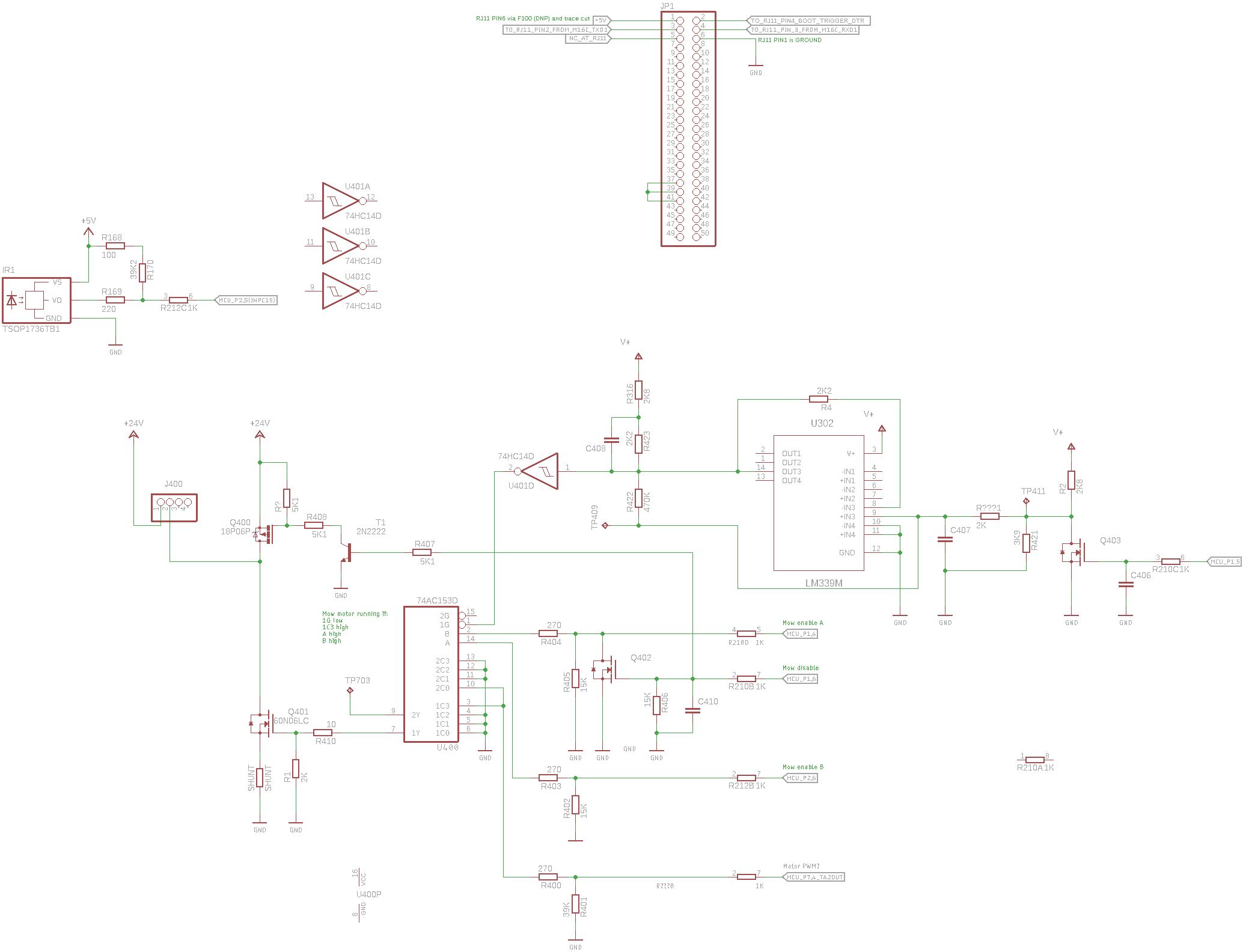
## Reverse engineered schematic in Kicad for PCG5000G1 mainboard used in the Robomow RM-400/City-110/RM-510 lawn mower
I had been repairing a Robomow RM-510 lawn mower which mowing motor does not works. Test fails with error 55.
*(In the case if you ran into the error 55 issue check the lid close checking Hall sensor...)*
The same board is present in the RM-200 (at least it is possible to set it in the service menu)
The main focus of my work is the mowing motor driving circuit:
Later on I started to dream about integrating the robot into [OpenMower](https://github.com/ClemensElflein/OpenMower).
Due to the limitations of the factry firmware at some point I would like to write a replacement firmware for it in [Mowgli style](https://github.com/cloudn1ne/Mowgli).
### IR remote
IR receiver type is unknown the following is present on it's back:
```
3
8 K
O S
C
```
### General thoughts
* MCU is clocked from a 16 MHz crystal
* IR remote receiver IC OC output is connected to the MCU's P2.5 pin (INPC15)
* Timer1 used for measuring time interupts on the INPC15
* Timer1 has 160 prescaler -> 1 timer increment == 10 us 100 kHz-n jár
* Timer1 CH5 set to measure time on both edges (`MOV.B #3, g1tmcr5 ; CH5 on IR input measure both edges`)
* Upon IC interrupt:
* The timer value (G1TM5) stored
* The time difference from the last impulse lenght is calculated (current width - prev width)
* Check if the current is longer than 4560 us + the previous
* Timer1 overflow interrupt generated when the 15th bit overflows (G1BCR0 IT set to 0)
* Timer1 overflow has a timeout counter variable which incremented in the overflows 2 times
* timer_counter_1,2, ir_timeout_counter counts 0-1-2 (after 0ms - 655,35ms - 1310,7ms)