Ecosyste.ms: Awesome
An open API service indexing awesome lists of open source software.
https://github.com/mr-ingenious/sixbtnmodulelib
6 buttons module arduino library for listening on button press events.
https://github.com/mr-ingenious/sixbtnmodulelib
arduino arduino-library arduino-sketch buttons electronics input pcb
Last synced: 15 days ago
JSON representation
6 buttons module arduino library for listening on button press events.
- Host: GitHub
- URL: https://github.com/mr-ingenious/sixbtnmodulelib
- Owner: mr-ingenious
- License: gpl-3.0
- Created: 2021-07-18T19:58:45.000Z (over 3 years ago)
- Default Branch: main
- Last Pushed: 2022-12-30T20:49:45.000Z (almost 2 years ago)
- Last Synced: 2023-07-29T13:43:04.392Z (over 1 year ago)
- Topics: arduino, arduino-library, arduino-sketch, buttons, electronics, input, pcb
- Language: C++
- Homepage:
- Size: 465 KB
- Stars: 0
- Watchers: 1
- Forks: 0
- Open Issues: 0
-
Metadata Files:
- Readme: README.md
- License: LICENSE
Awesome Lists containing this project
README
# SixBtnModuleLib
## Purpose
This arduino library is intended for use with an input module containing 6 pushbuttons and resistors forming a net of voltage dividers. The circuit only needs a single analog arduino pin. The button events can be measured with the arduino [analogRead()](https://www.arduino.cc/reference/en/language/functions/analog-io/analogread/) function.
## Hardware
The circuit contains six pushbuttons arranged like a star with a center button ("OK" button) and an extra button on the lower right corner ("BACK" button).
+------> Ucc (e.g. +3.3 V)
|
| +----> Ua (connect to analog pin on Arduino)
| |
| | +--> GND
| | |
+--O-O-O----------------------------------+
| |
| +---------+ |
| | | |
| | UP | |
| | | |
| +---------+ |
| |
| +---------+ +---------+ +---------+ |
| | | | | | | |
| | LEFT | | CENTER | | RIGHT | |
| | | | | | | |
| +---------+ +---------+ +---------+ |
| |
| +---------+ +---------+ |
| | | | | |
| | DOWN | | BACK | |
| | | | | |
| +---------+ +---------+ |
| |
+-----------------------------------------+
### Circuit design
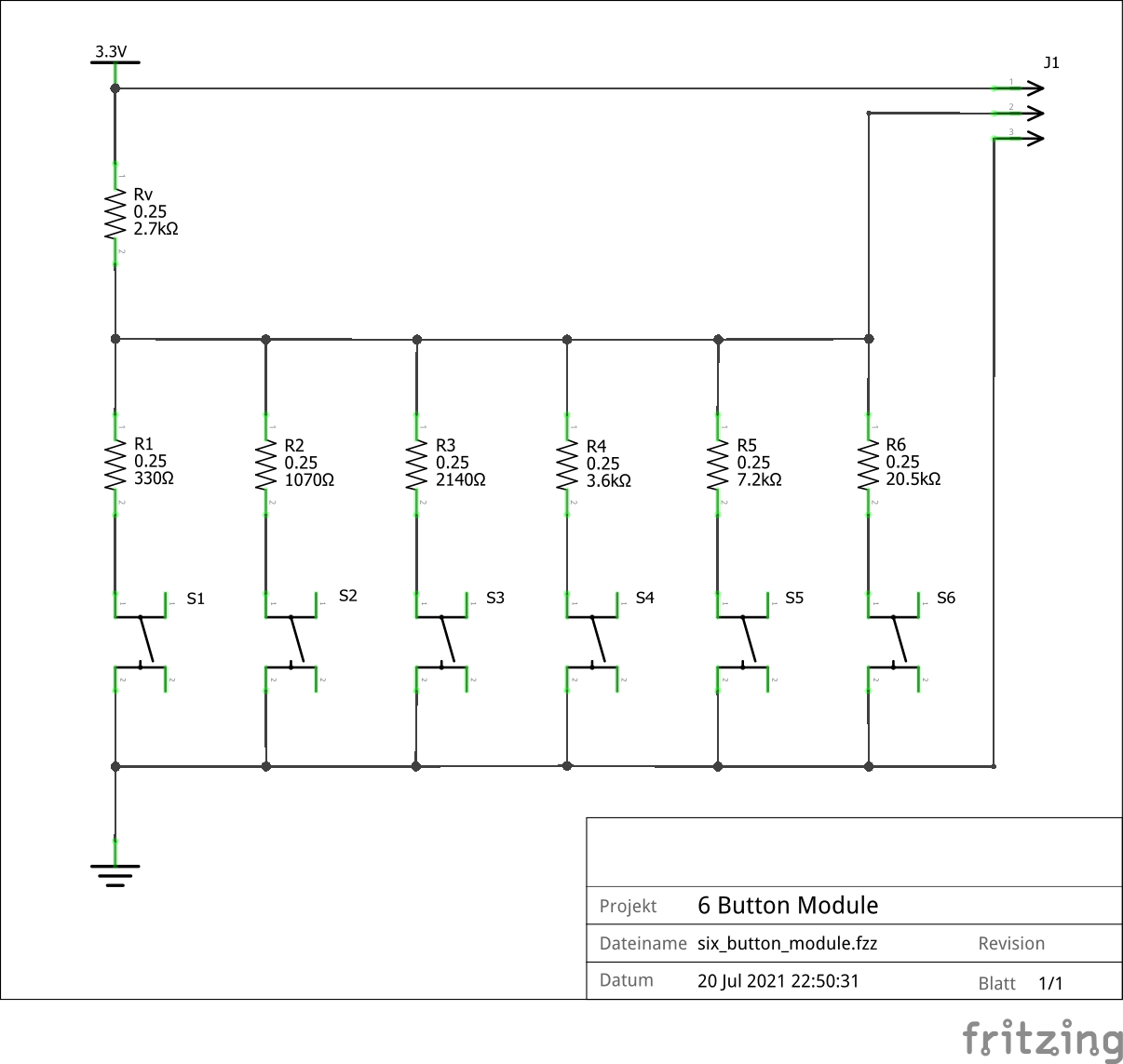
The circuit has three connectors, see J1:
1. Vcc for 3,3V (5V would also work)
2. Ua connected to the analog pin of the arduino
3. Ground
The series resistor Rv embodies the first part of the voltage divider. The other resistors have different values and are each connected to one pin of the pushbuttons and Rv. The different resistor values of R1 to R6 are explained below the schematic.
If a pushbutton has been pressed, a current flows through Rv and the resistor connected to the switch pressed. Example: If switch S3 is pressed, the current flows from Vcc through Rv and R3 to the ground. The J1 pin 2 is connected to the analog pin of the Arduino. The Arduino measures the voltage over resistor R3 and converts the measurement into a value between 0 and 1023. In the example, the voltage over R3 is somewhere around 1.4V (with Vcc = 3.3V). In this case, the arduino analogRead() function would return a value of approx. 440.

The resistors have different values which I chose with the following design goals:
1. The full resolution of the "analog in" pin is 1024, being capable of detecting differences of up to ~3 mV for each step (with 3.3V Vcc). To make use of the full range and for a reliable detection of the different pushbutton events, I divided the 1024 by 7, which is 146. This means, that pushing each of the pushbuttons returns a specific and roughly equal resistor voltage difference to the neighboring pushbuttons. Additionally, there is also some voltage distance to 0 and 1023.
For example, when pushing button 1, a value of 146 shall be returned by the arduino analogRead() function, pushing button 2 a value of 292 is calculated etc. up to a value of 877 for button 6.
2. The maximum current floating from Vcc to GND shall not exceed 5 mA. With 3.3V, the overall resistance must be more than 660 ohms.
The different resistance values for all the resistors can be calculated. I had to adapt the theoretical values with resistors I already had with nearly good resistor voltage differences for each of them, see below:
| Pushbutton | Resistor | Resistance [ohms]| Voltage over Rx [V] (1) | measured (2) |
| -- | -- | --------| --- | ---|
| - | Rv | 2.7k | 2,95 .. 0.4 |
| S1 (LEFT) | R1 | 330 | 0.35 | 108 |
| S2 (UP) | R2 | 1071 | 0.92 | 284 |
| S3 (CENTER) | R3 | 2140 | 1.43 | 445 |
| S4 (DOWN) | R4 | 3.6k | 1.86 | 577 |
| S5 (RIGHT) | R5 | 7.2k | 2.38 | 737 |
| S6 (BACK) | R6 | 20.5k | 2.90 | 901 |
Comments for the table:
(1) The voltage over Rx is the voltage drop between Ua and GND where the current flows through a resistor R1 to R6 depending on the button pressed, if Vcc 3.3V is applied to the circuit.
(2) The measured value is the value that is returned by the arduino analogRead() function if the respective button is pressed.
The calculated values to be measured are quite close to reality, that means, that my real circuit works as expected.
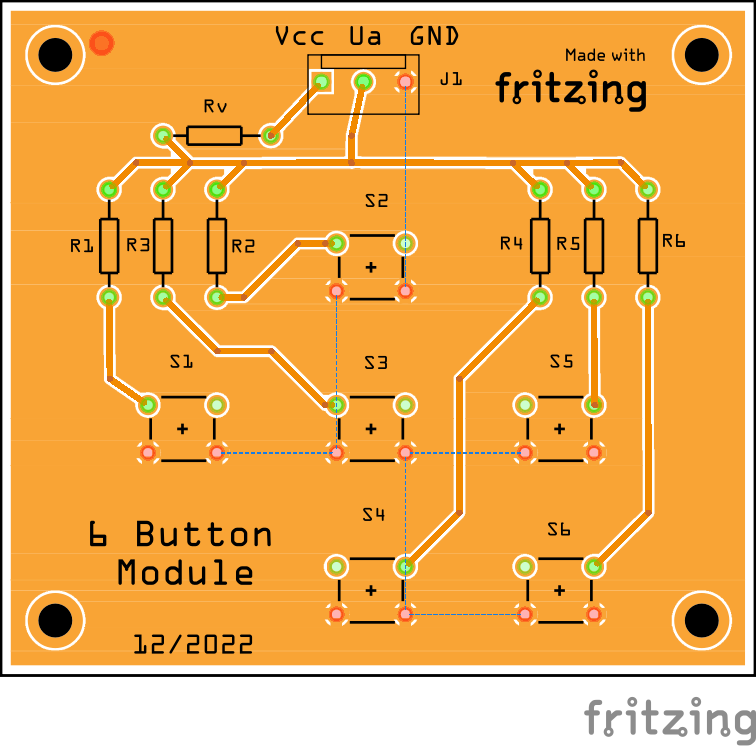
### PCB
The PCB looks like shown in the image below, which I did not realize. Instead, I used a perfboard and wired all parts manually.

## Software library
### Design goals
1. easy to use
2. does just one thing: read different pressed pushbuttons via analogread() and provide the correct button pressed
3. low memory footprint
4. fast
### Usage
The common use of the library is shown in the sketch located in the examples folder.
It is important, that the readButtons() function is cyclically called within the loop() function. Even though it can be called in every loop() cycle, it only executes internally after a defined time span "read interval" has exceeded. In case a button is pressed, the readButtons() method returns a byte value. If no button is pressed, it returns BUTTON_NONE, otherwise one of the following: BUTTON_LEFT, BUTTON_RIGHT, BUTTON_UP, BUTTON_DOWN, BUTTON_CENTER, BUTTON_BACK.
Readings are performed periodic based on the set value for the button read interval.
### Possible future extensions
- [ ] possibility to assign callback functions to buttons
- [ ] add possibility to distinguish between a pushbutton "click", "retrigger" and "hold"