https://github.com/mtrudel/rpi-breakout
A simple Raspberry Pi pHAT to break out common interfaces & GPIO
https://github.com/mtrudel/rpi-breakout
1-wire gpio i2c oshpark phat raspberry-pi uart
Last synced: about 2 months ago
JSON representation
A simple Raspberry Pi pHAT to break out common interfaces & GPIO
- Host: GitHub
- URL: https://github.com/mtrudel/rpi-breakout
- Owner: mtrudel
- Created: 2019-03-08T03:46:57.000Z (over 7 years ago)
- Default Branch: master
- Last Pushed: 2026-02-07T20:20:42.000Z (5 months ago)
- Last Synced: 2026-02-08T04:53:14.628Z (5 months ago)
- Topics: 1-wire, gpio, i2c, oshpark, phat, raspberry-pi, uart
- Homepage: https://oshpark.com/shared_projects/pOZPamMf
- Size: 218 KB
- Stars: 1
- Watchers: 0
- Forks: 1
- Open Issues: 0
-
Metadata Files:
- Readme: README.md
Awesome Lists containing this project
README
# Raspberry Pi Breakout Board
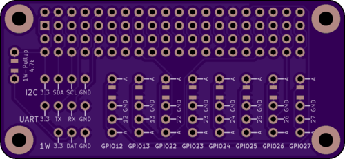
A simple Raspberry Pi pHAT to break out common interfaces & GPIO.
Available at [OSH Park](https://oshpark.com/shared_projects/pOZPamMf).
The board provides the following interfaces:
## 40 Pin Duplicate
The [40 pin header](https://pinout.xyz) is duplicated pin-for-pin; use this for one-off access to pins as needed.
## I2C
Breaks out the RPi's primary [I2C](https://pinout.xyz/pinout/i2c) interface (ie: not the EEPROM interface). Pinout is (from left to right looking at the top of the board):
* Pin 1: 3.3V
* Pin 2: I2C Data (RPi BCM2)
* Pin 3: I2C Clock (RPi BCM3)
* Pin 4: Ground
## UART
Breaks out the RPi's [UART](https://pinout.xyz/pinout/uart). Pinout is (from left to right looking at the top of the board):
* Pin 1: 3.3V
* Pin 2: Tx (RPi BCM14)
* Pin 3: Rx (RPi BCM15)
* Pin 4: Ground
## 1-Wire
Breaks out the RPi's [1-Wire](https://pinout.xyz/pinout/1_wire) interface. Pinout is (from left to right looking at the top of the board):
* Pin 1: 3.3V
* Pin 2: Data (RPi BCM4)
* Pin 3: Ground
The 1-Wire spec mandates a 4.7k pullup resistor on the data line; this can be done by populating the resistor marked `4.7k` on the left of the breakout board (there is provision to install either a through hole resistor or an 0805 SMD; both connections are wired in parallel)
## GPIO
Eight GPIOs are broken out, corresponding to BCM12-BCM13 and BCM22-BCM27. The pinout for each column is as follows (from top to bottom looking at the top of the board):
* Pin 1: In-line resistor terminal (common with pin 4)
* Pin 2: Ground
* Pin 3: GPIO pin (corresponds to BCMXX)
* Pin 4: In-line resistor terminal (common with pin 1)
This layout is a bit odd but allows each pin to be used either as an input (making use of the Pi's internal pullup resistors), or as an LED driver (by populating an optional resistor on each GPIO, detailed below).
### Using a GPIO as an input
1. Wire your sensor between pins 2 and 3 of the relevant GPIO column, and set the GPIO to use a pullup resistor in software.
2. The GPIO will be high when the sensor is open, and go low when the sensor closes.
In pictures:
```
O
O -----
|\ <-- switch
O -----
O
```
### Driving an LED
This comes with the usual caveats about driving LEDs directly off GPIO pins; so long as you're driving small LEDs in a non-continuous manner you should be fine, but caveat emptor etc.
1. Wire an appropriate (~ 300Ω) resistor between pins 1 and 2 of the relevant GPIO column (there is provision to install either a through hole resistor or an 0805 SMD; both connections are wired in parallel)
2. Wire your LED with the anode (longer leg) in pin 3 and the cathode (shorter leg) in pin 4.
3. You can now turn the LED on by driving the relevant GPIO output high.
In pictures:
```
O -----
|| <-- 330 ohm resistor
O -----
O ---------|\
| | <-- LED
O ------|/
```
# License
MIT