https://github.com/sarwanshah/hu_2017_8-bit-alu-using-logic-gates
This project presents the hardware design for an 8-bit arithmetic logic unit
https://github.com/sarwanshah/hu_2017_8-bit-alu-using-logic-gates
digital-logic-design
Last synced: 8 months ago
JSON representation
This project presents the hardware design for an 8-bit arithmetic logic unit
- Host: GitHub
- URL: https://github.com/sarwanshah/hu_2017_8-bit-alu-using-logic-gates
- Owner: SarwanShah
- License: gpl-3.0
- Created: 2025-01-29T03:44:04.000Z (9 months ago)
- Default Branch: main
- Last Pushed: 2025-02-07T22:50:21.000Z (8 months ago)
- Last Synced: 2025-02-07T23:25:34.435Z (8 months ago)
- Topics: digital-logic-design
- Homepage:
- Size: 325 KB
- Stars: 0
- Watchers: 1
- Forks: 0
- Open Issues: 0
-
Metadata Files:
- Readme: README.md
- License: LICENSE
Awesome Lists containing this project
README
# 8-bit Arithmetic Logic Unit (ALU)
## Project Overview
This project was developed under the **EE-172 Digital Logic and Design** course at **Habib University** during Fall 2017. It demonstrates the design and implementation of an **8-bit Arithmetic Logic Unit (ALU)** using fundamental **logic gates** and **integrated circuits (ICs)**. The ALU is the core computational unit of all digital computing devices, performing basic arithmetic and logic operations.
**REPORT: https://github.com/SarwanShah/8-bit-ALU-Using-Logic-Gates/blob/main/Project%20Report.pdf**
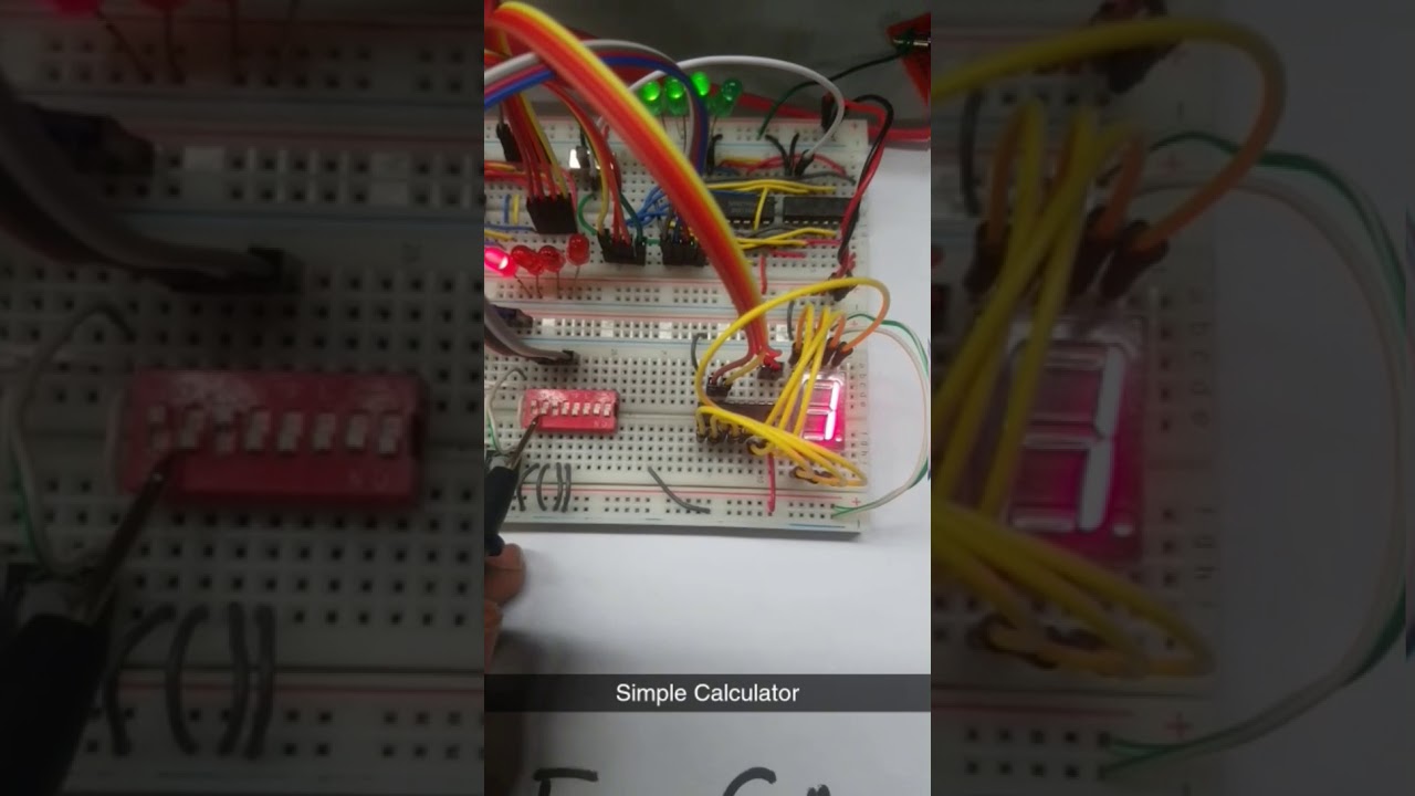
**VIDEO DEMONSTRATION:**
## 🛠 Features
- **Binary Addition** (4-bit full adder)
- **Binary Subtraction** (using 2’s complement)
- **Binary Multiplication** (via repeated addition and logic gates)
- **User Input Handling** (DIP switches and push buttons)
- **Clock Pulsing** (555 Timer IC for counter input)
- **7-Segment Display Output** (for multiplication results)
- **LED Output Indicators** (for addition/subtraction results)
## Project Implementation
### ➤ **Addition**
- Implemented using **74LS283 4-bit Full Adder IC**.
- Takes two 4-bit binary inputs from counters.
- Outputs a **4-bit sum** with a **1-bit carry**, displayed using LEDs.
### ➤ **Subtraction**
- Achieved using **two’s complement** logic.
- XOR gates (**74LS86**) invert the subtrahend when subtraction is selected.
- The full adder then adds the two numbers, displaying the result using LEDs.
### ➤ **Multiplication**
- Implemented using **AND gates** to generate partial products.
- **Half-adder circuits** (AND & XOR gates) sum the partial products.
- The final output is displayed on a **7-segment display** using a **BCD to 7-segment decoder IC (74LS47)**.
### ➤ **User Input & Clocking**
- **DIP Switches**: Used for direct binary input.
- **Push Buttons**: Used to increment counter inputs.
- **Toggle Switch**: Selects between different arithmetic operations.
- **555 Timer IC**: Generates clock pulses for **74LS93 4-bit binary counters**.
## Components Used
| Component | Description |
|-----------|------------|
| **74LS283** | 4-bit Full Adder IC |
| **74LS86** | XOR Gate IC (for subtraction & multiplication) |
| **74LS08** | AND Gate IC (for multiplication) |
| **74LS93** | 4-bit Binary Counter IC (user input handling) |
| **74LS47** | BCD to 7-segment Display Decoder |
| **555 Timer IC** | Generates clock pulses |
| **Push Buttons & Toggle Switch** | User controls |
| **7-Segment Display & LEDs** | Output visualization |
## Design Challenges
- **7-Segment Display Limitations**: Since standard 7-segment decoders do not support direct display of **4-bit binary numbers**, only the **multiplication output** is displayed this way.
- **Limited Cascading Options**: Decoding dual 7-segment outputs required complex logic beyond the project scope.
## Cost Effectiveness
The total cost of the project was **under PKR 1000**, as it utilized basic ICs and commonly available electronic components.
## Conclusion
This project serves as an **introductory digital logic** design exercise, helping students understand how **basic logic circuits** integrate into larger computational systems. Though simple, it provides hands-on experience with **binary arithmetic operations, digital logic design, and hardware troubleshooting**.