Ecosyste.ms: Awesome
An open API service indexing awesome lists of open source software.
https://github.com/simonrupf/extreme-feedback-blinker
A simple extreme feedback device (XFD) based on an ESP8266 microcontroller and one or multiple WS2812 Neopixels, providing an HTTP GET interface over WiFi
https://github.com/simonrupf/extreme-feedback-blinker
alarm arduino ci-cd cpp esp8266 esp8266-arduino extreme-feedback mcu neopixel wifi wifimanager ws2812 ws2812b
Last synced: 1 day ago
JSON representation
A simple extreme feedback device (XFD) based on an ESP8266 microcontroller and one or multiple WS2812 Neopixels, providing an HTTP GET interface over WiFi
- Host: GitHub
- URL: https://github.com/simonrupf/extreme-feedback-blinker
- Owner: simonrupf
- Created: 2019-06-11T18:46:11.000Z (over 5 years ago)
- Default Branch: master
- Last Pushed: 2019-09-16T17:17:33.000Z (over 5 years ago)
- Last Synced: 2024-12-01T00:42:36.875Z (about 2 months ago)
- Topics: alarm, arduino, ci-cd, cpp, esp8266, esp8266-arduino, extreme-feedback, mcu, neopixel, wifi, wifimanager, ws2812, ws2812b
- Language: C++
- Homepage:
- Size: 877 KB
- Stars: 2
- Watchers: 1
- Forks: 1
- Open Issues: 1
-
Metadata Files:
- Readme: README.md
Awesome Lists containing this project
README
# Extreme Feedback Blinker
A simple extreme feedback device (XFD) based on an ESP8266 microcontroller and
one or multiple WS2812 Neopixels, providing an HTTP GET interface over WiFi to
set the colors of the LEDs. The device is intended to be integrated into a CI/CD
or monitoring system providing a simple visual representation of the current
status.
## Usage
When first powered up, the WifiManager library will throw up a WLAN with SSID
"Blinker" and no password protection. When connecting to it using a WiFi enabled
device (notebook, smart phone, etc.), you should be redirected to a
configuration website that lets you select your main WLANs SSID and store the
WPA2 password on the microcontroller. Whenever the device is reset or powered up
*and* doesn't find the configured WiFi or fails to connect to it, it will return
to this configuration mode. The LED(s) should display red, blue, green as a test
pattern during this time.
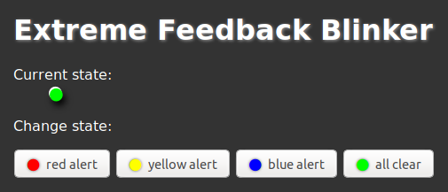
Once connected to configured WLAN, the LEDs should start to shimmer in the
default color. At this point in time you can connect to the device via a
webbrowser to see a page with multiple buttons to change the color of the LEDs.
You can find the IP of the device via your DHCP servers leases.

The color is controlled via a GET parameter called "color" and expects the 24
bit RGB color in hexadecimal notation (like in CSS). Click the example buttons
to see some URLs with the codes for the labeled colors. It should be easy to
integrate such a URL into your CI/CD or monitoring system or you can call it in
your shell scripts using curl or wget.
In a production setup you would want to persist the IP address of the device and
give it a resolvable hostname in your DNS, so that you can replace the device
without changing your CI/CDs or monitoring systems configuration. If possible,
keep the device on a segregated WiFi SSID apart from other users. Set up packet
filter rules to only allow the necessary host to access the devices port 80.
## Prerequisites
- Any ESP8266 module, i.e. NodeMCU or Wemos D1 mini, etc.
- Arduino IDE setup to support your particular module
- one or multiple WS281**2**, WS281**2b** or WS281**3** Neopixels that are 3.3 V
tolerant (not WS281**1**)
- jumper wires and bread board *or* light soldering skills and equipment
## Wiring
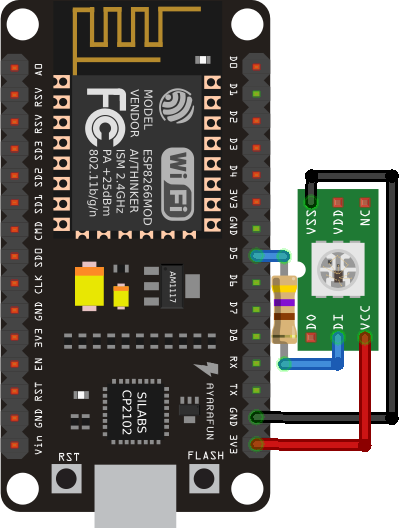
Example wiring of a NodeMCU with 470 Ohm resistor on the WS2812's data line:

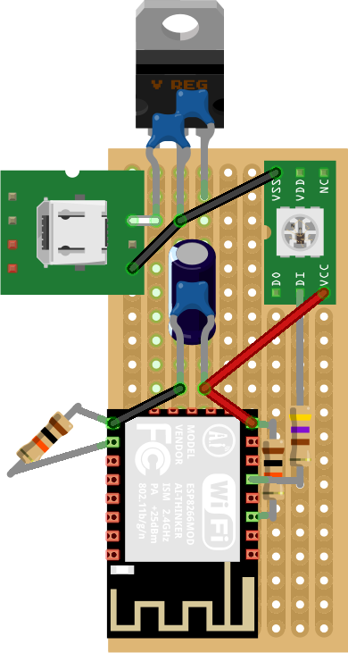
For a bare bones ESP-12 two pull-up/down resistors (10 kΩ) and a few capacitors
are needed when using 5 V USB power via a linear voltage regulator:

Capacitor ratings are:
- C1 100 nF (5 V to GND at voltage regulator)
- C2 2.2 µF (3.3 V to GND at voltage regulator)
- C3 470 µF (3.3 V to GND at ESP-12)
- C4 100 nF (3.3 V to GND at ESP-12)
Resistor ratings are:
- R3 10 kΩ (pull-down from ESP-12 GND to GPIO 15)
- R4 10 kΩ (pull-up from ESP-12 3.3 V to enable)
- R5 470 Ω (data line from ESP-12 GND to WS2812 data-in)
## Configuration
The Arduino sketch has a number of constants at the top that can be adjusted:
- `LED_NUM` - number of Neopixels you want to control, see note below
- `LED_PIN` - you can use any available digital pin to drive your pixels, pin
14 lends itself as one of the PWM capable pins
- `ANIMATION_DELAY` - ms to wait between each color change, decrease to speed up
the "breathing" animation of the colors
- `ANIMATION_MINIMUM` - the darkest the LEDs go before increasing their
brightness, if set to 0 the LEDs will briefly turn off each cycle
- If you have a FLORA version 1 Neopixel, you also have to change `NEO_GRB +
NEO_KHZ800` to `NEO_RGB + NEO_KHZ400`
> Note that while you may increase the number of pixels controlled, your NodeMCU
> powered via USB will probably not let you safely drive more then 5 pixels. For
> larger numbers please use an additional 3.3 V power supply, battery or similar
> and inject the power every 5 - 10 pixels or so. If using a power supply it is
> also advisable to add a large 1000 µF before the power gets injected to the
> pixels in order to prevent voltage bursts on power-up damageing your LEDs.
## Limitations
- By it's nature, black is displayed as the absence of light, so the LED will
appear off. In general dark colors will appear dimmer then brighter ones.
- All content is served over HTTP only.
- There is no authentication implemented, anyone with access to that network
can change the color.
- The microcontroller runs single-threaded and can only handle a single request
at a time.
- The configuration page used to set the password of your WPA2 secured WLAN is
served over an unsecured WiFi. The password is transmitted unencrypted.