https://github.com/techn0man1ac/simplebldc
Simple Arduino based 650W BLDC motor controller. Designed by KiCAD 9.
https://github.com/techn0man1ac/simplebldc
arduino bldc kicad motor motor-controller
Last synced: 20 days ago
JSON representation
Simple Arduino based 650W BLDC motor controller. Designed by KiCAD 9.
- Host: GitHub
- URL: https://github.com/techn0man1ac/simplebldc
- Owner: techn0man1ac
- License: mit
- Created: 2025-04-06T16:52:29.000Z (about 1 year ago)
- Default Branch: main
- Last Pushed: 2025-05-19T17:31:10.000Z (about 1 year ago)
- Last Synced: 2025-05-19T18:41:02.511Z (about 1 year ago)
- Topics: arduino, bldc, kicad, motor, motor-controller
- Language: C++
- Homepage:
- Size: 28 MB
- Stars: 0
- Watchers: 1
- Forks: 0
- Open Issues: 0
-
Metadata Files:
- Readme: README.md
- License: LICENSE
Awesome Lists containing this project
README
# SimpleBLDC
This is simple Arduino based 650W BLDC motor(with Hall sensors) controller. Designed with [KiCAD](https://www.kicad.org/). This controller has version V0.1, which means it is still under development. **The source files can be changed.**
Simple BLDC 3-Phase BLDC motor driver specs:
- Battery: 8S
- VCC: 24.0V to 33.6V
- I(max): 20A
- Сurrent measurements per phase
The device has the following features:
- XT60 power connector;
- Arduino Nano V3.0 main controller;
- Overcurrent protection (fuse);
- Reverse polarity protection;
- The ability to work with non-collector motors via Hall sensors (electric scooter or electric bicycle);
- Monitoring and control of the current of each phase (current is measured in both positive and negative directions);
- Current control by PWM, operating frequency 16/32 kHz;
- Has a connector for connecting a traction control potentiometer and a reverse button.
- Publication of the project under the [MIT license](https://github.com/techn0man1ac/SimpleBLDC/blob/main/LICENSE).
# Schematic
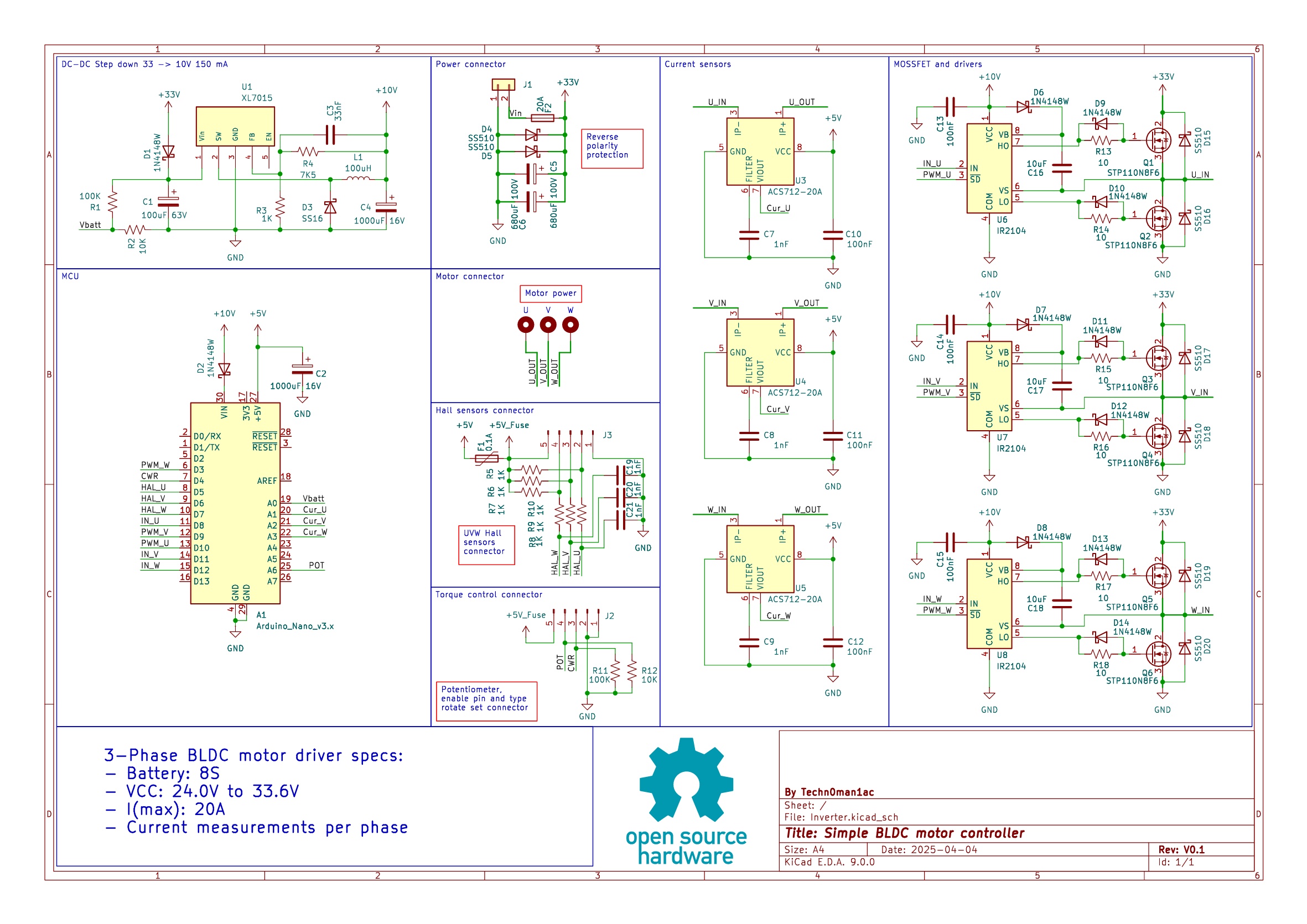
The device has 3 drivers for mosfet transistors, as well as 3 current sensors based on the Hall effect, which measure both in the positive and negative directions. The use of 3 sensors is the reason for the development of the device for regenerative braking.
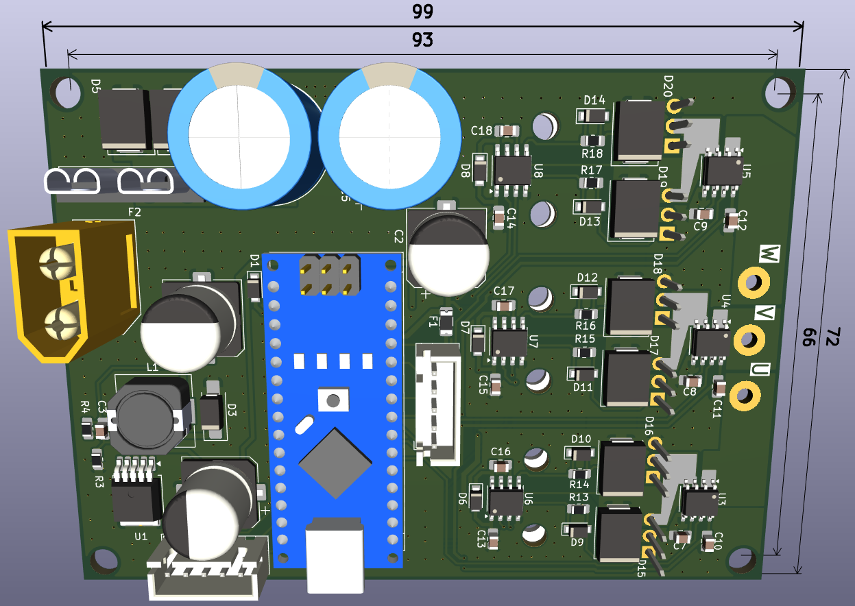
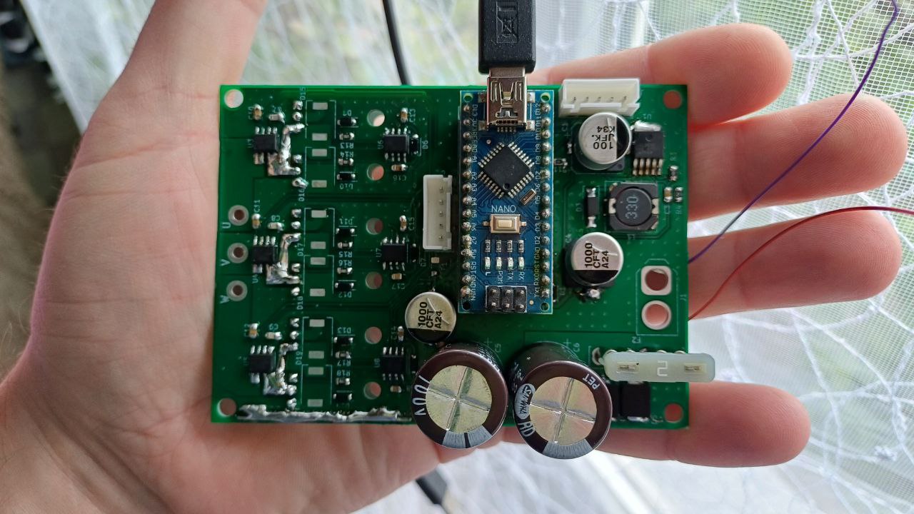
# PCB
The board consists of two layers: top and bottom. All the main parts are located on the top layer.

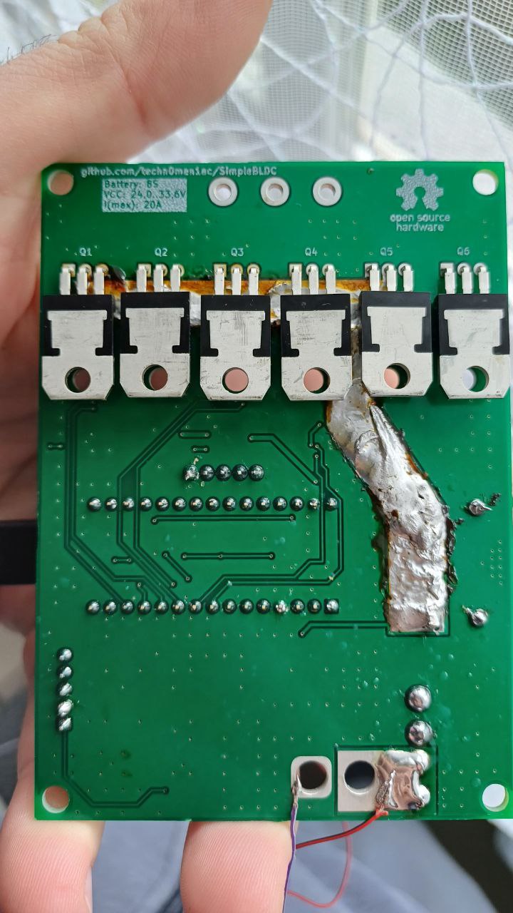
The bottom layer contains mainly earth and power tracks.
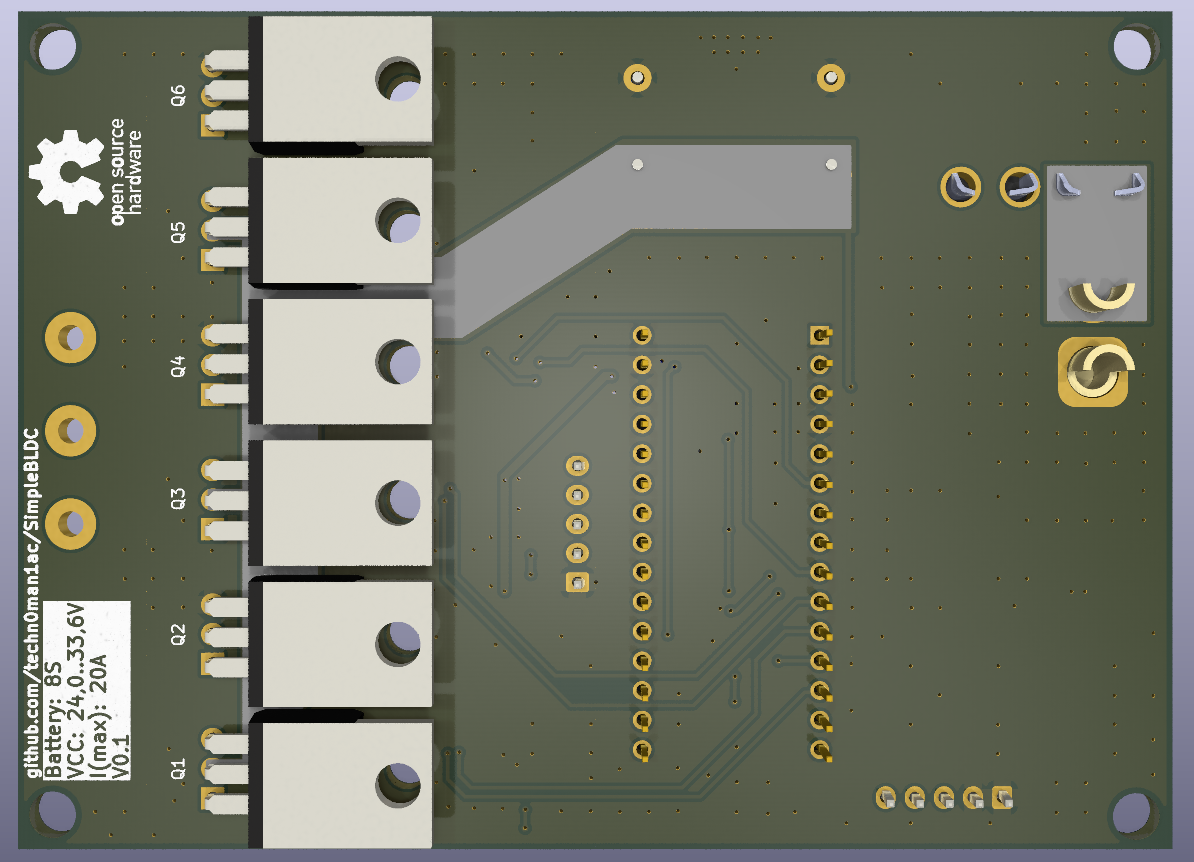
Board sizes is 72 x 99 mm: