https://github.com/tobozo/esp32-dcf77_analyzer_clock
⏰ An ESP32 TFT interpretation of the @deruiter's DCF77-Analyzer-Clock-V2.0
https://github.com/tobozo/esp32-dcf77_analyzer_clock
arduino atomic-clock dcf77 esp32 esp32-chimera-core weather
Last synced: about 1 year ago
JSON representation
⏰ An ESP32 TFT interpretation of the @deruiter's DCF77-Analyzer-Clock-V2.0
- Host: GitHub
- URL: https://github.com/tobozo/esp32-dcf77_analyzer_clock
- Owner: tobozo
- License: mit
- Created: 2019-08-21T00:29:46.000Z (almost 7 years ago)
- Default Branch: master
- Last Pushed: 2023-05-19T11:41:26.000Z (about 3 years ago)
- Last Synced: 2025-02-25T13:41:43.992Z (over 1 year ago)
- Topics: arduino, atomic-clock, dcf77, esp32, esp32-chimera-core, weather
- Language: C
- Homepage:
- Size: 23.6 MB
- Stars: 25
- Watchers: 7
- Forks: 8
- Open Issues: 7
-
Metadata Files:
- Readme: README.md
- License: LICENSE
Awesome Lists containing this project
README
# esp32-DCF77_Analyzer_Clock
An ESP32 TFT interpretation of the @deruiter's [DCF77-Analyzer-Clock-V2.0](https://github.com/deruiter/DCF77-Analyzer-Clock-V2.0)
[](https://www.youtube.com/watch?v=TQnQEQfLkGE)
Hardware Requirements:
----------------------
- ESP32
- TFT (160*128 minimum recommended, working on elastic design to cover higher resolutions)
- DCF77 Atomic clock module ( such as this one https://www.universal-solder.ca/product/canaduino-60khz-atomic-clock-receiver-module-wwvb-msf-jjy60/ (WWVB/JJY60/MSF/DCF77) or https://www.pollin.de/p/dcf-77-empfangsmodul-dcf1-810054 (DCF77))
- RTC Module (preferably i2c, e.g. a 5V DS1307 or 3V3 DS3231)
- Buttons (optional)
- Speaker (optional)
Software Requirements:
----------------------
- M5Stack Core or ESP32-Chimera-Core for compatibility https://github.com/tobozo/ESP32-Chimera-Core (replaces M5Stack Core, adds support for Odroid-Go, TTGO-TS, Wrover-Kit LoLin D-32Pro)
- Bodmer's JPEGDecoder for rendering jpeg in sprites https://github.com/Bodmer/JPEGDecoder
Running on an ODROID-GO:
------------------------
(Contributed by [dl9sec](https://github.com/dl9sec))
Thanks to the ESP32-Chimera-Core, the clock runs fine and flawless on an ODROID-GO (with sound output and buttons support for A/B/MENU).
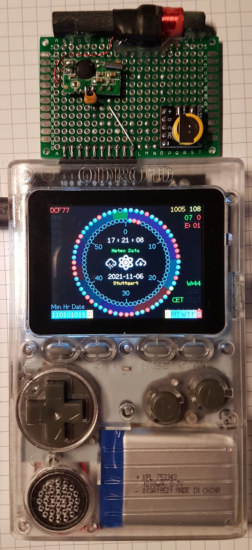
The hardware components has to be connected to the ODROID-GO's 10-pin connector:
- The DCF modules positive pulse output has to be connected to `IO4` (5).
- The RTC should be a DS3231 for convenience (3V3 system). Connect the supply pins to the ODROID-GO `P3V3` (6) and `GND` (1), `SDA` to `IO15` (4) and SCL to `IO12` (3) (hopefully the RTC will never need to do a clock stretching, because `IO12` is a buffered output pin, not an open-collector/-drain).
To build a suitable ODROID-GO firmware file the following steps have to be proceeded:
- Uncomment the `#define CONFIG_OGO` in the `Config.h` (comment out any other of the platforms).
- Activate the verbose compiler output at the Arduino IDE preferences.
- Select the `ORDOID ESP32` as target in the Arduiono IDE.
- Build the firmware (just clicking the checkmark).
- When successfully finished the build process, watch one of the last lines of the Arduino IDE console output and navigate to the temporary directory where the compiler puts the file `esp32-DCF77_Analyzer_Clock.ino.elf`.
- There you will find a file named **`esp32-DCF77_Analyzer_Clock.ino.bin`**. Copy this file to a directory (of your choice), where the executable `mkfw` (Linux) or `mkfw.exe` (Windows, get it here: [https://forum.odroid.com/viewtopic.php?t=31939](https://forum.odroid.com/download/file.php?id=9325&sid=f3db9325d02e3d69aa28fcd5d3e3a064)) could be found.
- Copy the file `\assets\img\OGO_DCF77_Analyzer_Clock_Logo.raw` to the same directory (icon file created as described [here](https://wiki.odroid.com/odroid_go/arduino_app#make_tile_image_with_ffmpeg)).
- Create the firmware with `mkfw "DCF77 Anylyzer Clock" OGO_DCF77_Analyzer_Clock_Logo.raw 0 16 1048576 app esp32-DCF77_Analyzer_Clock.ino.bin` (Windows) or `./mkfw "DCF77 Anylyzer Clock" OGO_DCF77_Analyzer_Clock_Logo.raw 0 16 1048576 app esp32-DCF77_Analyzer_Clock.ino.bin` (Linux).
- Rename the file with `ren firmware.fw esp32-DCF77_Analyzer_Clock.fw` (Windows) or `mv firmware.fw esp32-DCF77_Analyzer_Clock.fw` (Linux).
- Put the firmware file `esp32-DCF77_Analyzer_Clock.fw` to your ODROID-GO's SD card in the `odroid\firmware` folder and install it from there to your ODROID-GO.
- After a software reboot you need to power the ODROID-GO off and on again to re-init the incomplete graphics.
CREDITS:
--------
I learned a lot from Erik de Ruiter who learned a lot from the work of Matthias Dalheimer and Thijs Elenbaas
who made their own DCF77 decoders.
Although the changes I made are far from optimistic, this code has wisdom DNA in its roots!
Without the incredible work of these geniuses I would not have known where to start and how to write those credits :)
Huge thanks to [@BrettOliver](https://github.com/brettoliver) for fueling the code with a 320x240 UI, implementing the leap second, and [much more](http://www.brettoliver.org.uk/DCF77_Signal_Generator_Analyzer/DCF77_Signal_Generator.htm#leapsecond)
Author:
-------
- https://github.com/tobozo/
- https://twitter.com/tobozotagada/
- https://www.youtube.com/c/tobozotagada
Interesting websites:
---------------------
- Inspirational video : https://www.youtube.com/watch?v=ZadSU_DT-Ks
- UI code based on : https://github.com/deruiter/DCF77-Analyzer-Clock-V2.0
- Crypto code based on : https://github.com/FroggySoft/AlarmClock
- Weather code based on : http://arduino-projects4u.com/home-weather-station/
- Erik de Ruiter : https://www.hackster.io/edr1924
- Brett Oliver : http://www.brettoliver.org.uk/
- Joop Tap : http://www.jooptap.nl
- Thijs Ellenbaas : http://thijs.elenbaas.net/2012/04/arduino-dcf77-radio-clock-receiver-hardware-2/
- Mathias Dalheimer : https://github.com/roddi/DCF77-Arduino/blob/master/DCF77Servoclock/DCF77.h
- DCF77 wikipedia : https://en.wikipedia.org/wiki/DCF77
- Much more DCF77 info : http://www.picbasic.nl/indexes_uk.htm
- Erik de Ruiter's Flickr : https://www.flickr.com/photos/edr1924/albums
- Erik de Ruiter's Github : https://github.com/deruiter
- FroggySoft's Github : https://github.com/FroggySoft