https://github.com/todbot/pico_test_synth
Simple board to help make synths with Raspberry Pi Pico/Pico2 and PCM5102 I2S DAC
https://github.com/todbot/pico_test_synth
circuitpython i2s raspberrypipico rp2040 rp2350 synthdiy synthesizer synthio
Last synced: 11 months ago
JSON representation
Simple board to help make synths with Raspberry Pi Pico/Pico2 and PCM5102 I2S DAC
- Host: GitHub
- URL: https://github.com/todbot/pico_test_synth
- Owner: todbot
- License: mit
- Created: 2023-08-08T05:34:05.000Z (almost 3 years ago)
- Default Branch: main
- Last Pushed: 2025-06-09T19:23:44.000Z (about 1 year ago)
- Last Synced: 2025-08-17T23:43:24.942Z (11 months ago)
- Topics: circuitpython, i2s, raspberrypipico, rp2040, rp2350, synthdiy, synthesizer, synthio
- Language: Python
- Homepage:
- Size: 3.25 MB
- Stars: 44
- Watchers: 2
- Forks: 2
- Open Issues: 0
-
Metadata Files:
- Readme: README.md
- License: LICENSE
Awesome Lists containing this project
README
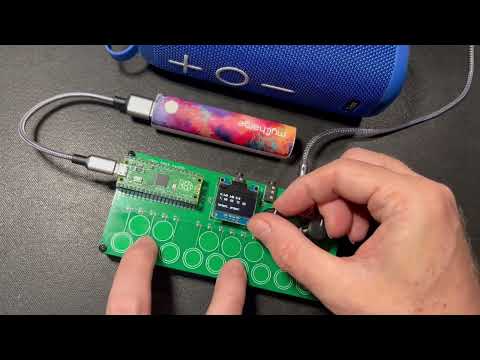
# pico_test_synth
A simple
[Raspberry Pi Pico RP2040 or Pico 2 RP2350](https://www.raspberrypi.com/documentation/microcontrollers/raspberry-pi-pico.html)-based
synth to experiment with [`synthio`](https://github.com/todbot/circuitpython-synthio-tricks) and [Mozzi](https://github.com/sensorium/Mozzi).

### pico_test_synth2


### pico_test_synth, the original


video demo
[](https://www.youtube.com/watch?v=9U2Dn7ckdbs)
** **[Available on Tindie](https://www.tindie.com/products/todbot/pico_test_synth/)** **
### Features
* [PCM5102 I2S DAC](https://todbot.com/blog/2023/05/16/cheap-stereo-line-out-i2s-dac-for-circuitpython-arduino-synths/) footprint for high-quality stereo audio out
* Optoisolated MIDI Input via [MIDI TRS-A 3.5mm jack](https://www.perfectcircuit.com/make-noise-0-coast-midi-cable.html)
* MIDI output via MIDI TRS-A 3.5mm jack
* Two pots for controlling parameters
* One switch for controlling parameters
* 16 capsense touch buttons for synth triggering
* USB MIDI in/out of course too
* **(NOTE: the pico_test_synth1 PCB will NOT work with the Pico2, since its RP2350 chip has a hardware error)**
#### pico_test_synth2 vs pico_test_synth
- Both use the same components
- Both run the same code
- Both fit in the same enclosure
- `pico_test_synth2` drawn in Kicad; `pico_test_synth` drawn in Eagle
- `pico_test_synth2` has square buttons; `pico_test_synth` has round buttons
- `pico_test_synth2` can work with Pico 2 and Pico
- `pico_test_synth` can only work with Pico1
### Software
Programs written for [`qtpy_synth`](https://github.com/todbot/qtpy_synth/)
will work with this board too with minimal changes.
Some programs written specifically for this board:
* [hwtest](https://github.com/todbot/pico_test_synth/tree/main/circuitpython/hwtest/code.py) - test out the hardware with a simple synth ([video demo](https://www.youtube.com/watch?v=9U2Dn7ckdbs))
* [wavesynth](https://github.com/todbot/pico_test_synth/tree/main/circuitpython/wavesynth/) - port of wavesynth for qtpy_synth board with some improvements
* [TBish](https://github.com/todbot/pico_test_synth/tree/main/circuitpython/tbish/) - a TB303-like synth demo ([video demo](https://www.youtube.com/watch?v=1AflpXbEIno))
* [monosynth1](https://github.com/todbot/pico_test_synth/tree/main/arduino/monosynth1) - a full Moog-like monosynth written in Arduino & Mozzi
#### See also:
- [CircuitPython Synthio Tricks](https://github.com/todbot/circuitpython-synthio-tricks)
- Contains [many other synthio examples](https://github.com/todbot/circuitpython-synthio-tricks/tree/main/examples) that can work with this synth with minimal changes
- [Synthio Tutorial](https://todbot.github.io/CircuitPython_Synthio_Tutorial/)
- a getting-started guide for `synthio` ending with some full synthesiser voices
### Enclosure
As seen in the photos, there is a simple [3d-printable enclosure available on Printables](https://www.printables.com/model/784414-case-for-pico_test_synth-circuitpython-synthesizer).
It's fast to print and you can snap the PCB in to quickly get started,
or use M2.5 screws and nuts to secure the PCB more permanently.
### Pins used
The board uses all of the Raspberry Pi Pico pins:
* `board.GP28` - middle button
* `board.GP27` - right knob
* `board.GP26` - left knob
* `board.GP22` - I2S data
* `board.GP21` - I2S LR clock
* `board.GP20` - I2S bit clock
* `board.GP19` - I2C SCL for OLED display
* `board.GP18` - I2C SDA for OLED display
* `board.GP17` - TRS UART MIDI in
* `board.GP16` - TRS UART MIDI out
* `board.GP15`..`board.GP0` -- touch pads 1-16
For more details see [`hwtest/code.py`](https://github.com/todbot/pico_test_synth/tree/main/circuitpython/hwtest/code.py).
### Schematics
#### pico_test_synth2 ####
[ ](./schematics/pico_test_synth2/pico_test_synth2_sch.pdf)
#### pico_test_synth, original ####
[ ](./schematics/pico_test_synth1/pico_test_synth1_sch.pdf)