https://github.com/vasikyrg/robotics-project-2021
My first project in Robotics in MATLAB
https://github.com/vasikyrg/robotics-project-2021
matlab robotics robotics-simulation
Last synced: 4 months ago
JSON representation
My first project in Robotics in MATLAB
- Host: GitHub
- URL: https://github.com/vasikyrg/robotics-project-2021
- Owner: vasikyrg
- Created: 2022-04-08T17:35:50.000Z (over 3 years ago)
- Default Branch: main
- Last Pushed: 2022-04-08T17:47:10.000Z (over 3 years ago)
- Last Synced: 2025-01-24T08:43:58.589Z (6 months ago)
- Topics: matlab, robotics, robotics-simulation
- Language: MATLAB
- Homepage:
- Size: 6.84 KB
- Stars: 0
- Watchers: 1
- Forks: 0
- Open Issues: 0
-
Metadata Files:
- Readme: README.md
Awesome Lists containing this project
README
# Robotics-Project-2021
My first project in Robotics in MATLAB (It is an effort to complete the project!)
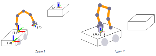
The robotic system of Figure 1 consists of a 6-degree freedom arm and a self-propelled platform on which the arm is mounted.he platform can move in any direction on the plane, as well as rotate around its z axis. Such a self-propelled platform can be modeled as a three-degree freedom robot with two prismatic and one rotary hinge, 𝑞𝑚 = [𝑥, 𝑦, 𝜑𝑧]. The dimensions of the platform are 0.75x1x0.5m.
One of the scenarios for using this robotic system is to pick up and move objects, as shown in Figures 1 and 2, from the table to the platform. A cylindrical object 10cm high and with a radius of 2.5cm with a frame {A., Located in the center of the lower base of the object, is placed in the center of the surface of a table measuring 0.35x0.35x0.6m. Obtaining the object is achieved when the position of the edge frame {E στεί is identified with a suitable position in relation to the frame {A} and the z-axes of the two frames have the same direction. Accordingly, the transport of the object and its placement on the platform is achieved when the position of the frame of the object {A συνέχεια is then identified with the frame {F}. The frame {F} is located in the center of the upper surface of the platform and has the same orientation as the frame of the platform {M} located in the center of its lower surface, as shown in Figures 1 and 2. The frame of the platform {M} identifies with the inertial frame {0} in the initial position.
The position and orientation (in Quaternion) of the frame of the object {A} with respect to the inertial frame {0} is given by:
𝑝0𝛢 = [1.5 1.5 0.6]^𝑇, 𝑄0𝛢 = [1 0 0 0]^𝑇
The position and orientation of the base frame of the robot {B} with respect to the platform {M} is given by:
𝑝𝛭𝛣 = [0.0 0.35 0.5]^𝑇, 𝑄𝛭𝛣 = [1 0 0 0]^𝑇
The arm receives hinge speed commands, while the platform receives body speed commands. Suppose that the robot joints have a starting position:
𝑞0 = [2.6180 −0.6695 1.2719 3.1416 1.2002 −0.9821]^𝑇

The model of the arm is given in the file lwr_create.p.
-> Simulate and visualize the movement of the arm in a 3D virtual environment.
Suggestions:
1) In case of excess degrees of freedom to use the pinv function instead of inv.
2) For the numerical integration (simulation) of differential equations use Euler integration with step 𝑑𝑡≤10𝑚𝑠.
3) Use the robotics toolbox: https://petercorke.com/toolboxes/robotics-toolbox/
Given:
lwr_create.p: returns an LWR robot object with 6 degrees of freedom. You call it without arguments lwr = lwr_create (). Requires the robotics toolbox.