https://github.com/wagiminator/ch32v003-ir-remote
Simple 5-Button IR Remote Control
https://github.com/wagiminator/ch32v003-ir-remote
ch32v003 ir remote-control risc-v wch
Last synced: 12 months ago
JSON representation
Simple 5-Button IR Remote Control
- Host: GitHub
- URL: https://github.com/wagiminator/ch32v003-ir-remote
- Owner: wagiminator
- License: other
- Created: 2024-07-31T15:47:29.000Z (almost 2 years ago)
- Default Branch: main
- Last Pushed: 2024-11-24T11:16:57.000Z (over 1 year ago)
- Last Synced: 2025-03-26T06:19:25.986Z (over 1 year ago)
- Topics: ch32v003, ir, remote-control, risc-v, wch
- Language: C
- Homepage: https://oshwlab.com/wagiminator/ch32v003-tinyremote
- Size: 1.35 MB
- Stars: 11
- Watchers: 1
- Forks: 1
- Open Issues: 1
-
Metadata Files:
- Readme: README.md
- License: LICENSE
Awesome Lists containing this project
README
# TinyRemote - IR Remote Control based on CH32V003
TinyRemote is a very simple 5-button IR remote control based on the cost-effective CH32V003 RISC-V microcontroller powered by a CR2032 or LIR2032 coin cell battery.
- Project Video (YouTube, ATtiny13A version): https://youtu.be/ad3eyNCov9c

For the ATtiny13A-based version of the IR remote control visit [TinyRemote](https://github.com/wagiminator/ATtiny13-TinyRemote). For the 12-button version of the ATtiny13A-based IR remote control see [TinyRemoteXL](https://github.com/wagiminator/ATtiny13-TinyRemoteXL).
# Hardware
## Schematic

## The CH32V003 Family of 32-bit RISC-V Microcontrollers
The CH32V003 series is a collection of industrial-grade general-purpose microcontrollers that utilize the QingKe RISC-V2A core design supporting the RV32EC instruction set. These microcontrollers are equipped with various features such as a 48MHz system main frequency, 16KB flash, 2KB SRAM, 2.7V - 5.5V supply voltage support, a single-wire serial debug interface, low power consumption, and an ultra-small package. Additionally, the CH32V003 series includes a built-in set of components including a DMA controller, a 10-bit ADC, op-amp comparators, multiple timers, and standard communication interfaces such as USART, I2C, and SPI.
## Building Instructions
1. Take the Gerber files (the *zip* file inside the *hardware* folder) and upload them to a PCB (printed circuit board) manufacturer of your choice (e.g., [JLCPCB](https://jlcpcb.com/)). They will use these files to create the circuit board for your device and send it to you.
2. Once you have the PCB, you can start soldering the components onto it. Use the BOM (bill of materials) and schematic as a guide to make sure everything is connected correctly. You can find the corresponding files in the *hardware* folder.
3. Upload the firmware by following the instructions in the next section (see below).
4. To create the case for your device, use the *stl* files in the *3dprint* folder with your 3D printer.
# Software
There are various communication protocols for infrared remote controls, most of which use a carrier wave between 30kHz and 58kHz, depending on the protocol. This carrier wave is generated using pulse-width modulation (PWM) at the IR diode, helping the receiver distinguish the signal from noise. The IR signal is modulated onto the carrier wave using pulse code modulation (PCM) by turning the IR LED on and off in a specific pattern. The telegrams consist of a start frame, the receiver's device address, and the command for the key pressed. This IR Remote Control implements the four most widely used protocols:
|Protocol|Carrier Frequency|Encoding Method|Start Frame|Address|Command|
|:-|:-|:-|:-|:-|:-|
|NEC|38kHz|Pulse Distance|9ms burst / 4.5ms space|8/16 bits|8 bits|
|Samsung|38kHz|Pulse Distance|4.5ms burst / 4.5ms space|8 bits|8 bits|
|RC-5|36kHz|Manchester|Start bits|5 bits|6/7 bits|
|Sony SIRC|40kHz|Pulse Length|2.4ms burst / 0.6ms space|5/8/13 bits|7 bits|
## NEC Protocol
Timer1 generates a 38kHz carrier frequency with a 25% duty cycle on the output pin connected to the IR LED. The IR telegram is modulated by toggling the IR LED pin between output high and output alternate. Setting the pin to output alternate enables PWM on this pin, sending a burst of the carrier wave. Setting the pin to output high turns off the LED completely.
The NEC protocol uses pulse distance encoding, where a data bit is defined by the time between bursts. A "0" bit consists of a 562.5µs burst (LED on: 38kHz PWM) followed by a 562.5µs space (LED off). A "1" bit consists of a 562.5µs burst followed by a 1687.5µs space.
An IR telegram starts with a 9ms leading burst followed by a 4.5ms space. Then, four data bytes are transmitted, with the least significant bit first. A final 562.5µs burst signifies the end of the transmission. The four data bytes are transmitted in the following order:
- the 8-bit address for the receiving device,
- the 8-bit logical inverse of the address,
- the 8-bit command, and
- the 8-bit logical inverse of the command.
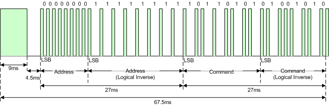
The Extended NEC protocol uses 16-bit addresses. Instead of sending an 8-bit address and its logical inverse, it sends the low byte first, followed by the high byte of the address.
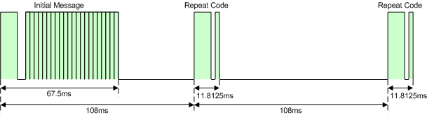
If the remote control button is held down, a repeat code is sent. This code consists of a 9ms leading burst, a 2.25ms pause, and a 562.5µs burst to mark the end. The repeat code is sent every 108ms until the button is released.
## Samsung Protocol
The SAMSUNG protocol corresponds to the NEC protocol, except that the start pulse is 4.5ms long and the address byte is sent twice. The telegram is repeated every 108ms as long as the button is pressed.
## Philips RC-5 Protocol
The Philips RC-5 protocol uses Manchester encoding with a 36kHz carrier frequency. A "0" bit is an 889µs burst followed by an 889µs space, while a "1" bit is an 889µs space followed by an 889µs burst.
An IR telegram starts with two start bits: the first bit is always "1", and the second bit is "1" in the original protocol or the inverted 7th bit of the command in the extended RC-5 protocol. The third bit toggles after each button release. The next five bits are the device address, and the last six bits are the command, all transmitted with the most significant bit (MSB) first.
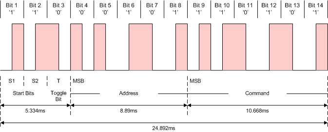
As long as a key remains down the telegram will be repeated every 114ms without changing the toggle bit.
## Sony SIRC Protocol
The Sony SIRC protocol uses pulse length encoding with a carrier frequency of 40kHz. A "0" bit consists of a 600µs burst followed by a 600µs space, while a "1" bit consists of a 1200µs burst followed by a 600µs space. An IR telegram starts with a 2400µs leading burst followed by a 600µs space. The command and address bits are then transmitted, with the least significant bit (LSB) first. The specifics of the command and address bits depend on the protocol version as follows:
- 12-bit version: 7 command bits, 5 address bits
- 15-bit version: 7 command bits, 8 address bits
- 20-bit version: 7 command bits, 5 address bits, 8 extended bits
As long as a key remains down the telegram will be repeated every 45ms.
## Power Saving
The code uses the standby power-down function, waking up whenever a button is pressed, triggered by a pin falling edge event.
While no button is pressed, the CH32V003 stays in standby power-down mode, consuming about 9µA at 3V. A typical CR2032 battery has a capacity of 230mAh, resulting in a theoretical battery life of over 25,000 hours, or nearly 3 years. However, actual battery life will be shorter due to self-discharge. When a button is pressed, the current can spike up to 25mA. The diagram below shows the current consumption when a button is pressed and an NEC telegram is sent, measured with the [Power Profiler Kit II](https://www.nordicsemi.com/Products/Development-hardware/Power-Profiler-Kit-2):
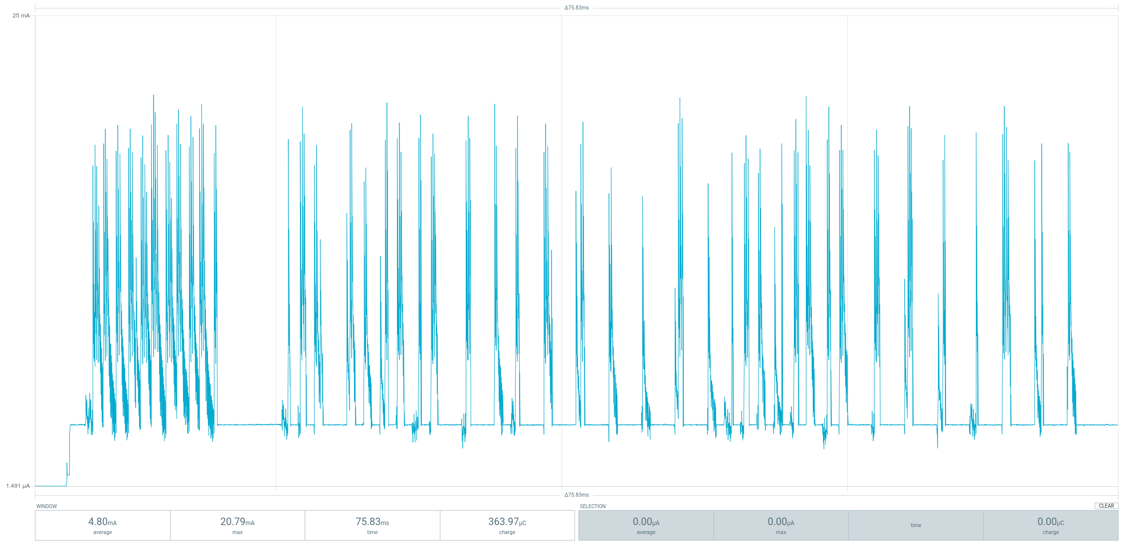
When sending a NEC telegram, the current consumption averages around 5mA for 71ms. In theory, a single battery could send more than 2 million telegrams. However, rechargeable LIR2032 batteries have a much lower capacity.
By the way, although 9µA in standby mode seems low, the [ATtiny13A](https://github.com/wagiminator/ATtiny13-TinyRemote) uses only about 150nA, which is 60 times less!
# Compiling and Uploading Firmware
## Defining the Key Commands
Before compiling and uploading the firmware, the desired IR commands must be assigned to the respective buttons. This is done by editing the *config.h* file. Multiple commands of different protocols can be assigned to a single button. These commands should be separated by semicolons. When the button is pressed, the commands will be executed sequentially.
## Programming and Debugging Device
To program the CH32V003 microcontroller, you will need a special programming device which utilizes the proprietary single-wire serial debug interface (SDI). The [WCH-LinkE](http://www.wch-ic.com/products/WCH-Link.html) (pay attention to the "E" in the name) is a suitable device for this purpose and can be purchased commercially for around $4. This debugging tool is not only compatible with the CH32V003 but also with other WCH RISC-V and ARM-based microcontrollers.

To use the WCH-LinkE on Linux, you need to grant access permissions beforehand by executing the following commands:
```
echo 'SUBSYSTEM=="usb", ATTR{idVendor}=="1a86", ATTR{idProduct}=="8010", MODE="666"' | sudo tee /etc/udev/rules.d/99-WCH-LinkE.rules
echo 'SUBSYSTEM=="usb", ATTR{idVendor}=="1a86", ATTR{idProduct}=="8012", MODE="666"' | sudo tee -a /etc/udev/rules.d/99-WCH-LinkE.rules
sudo udevadm control --reload-rules
```
On Windows, if you need to you can install the WinUSB driver over the WCH interface 1 using the [Zadig](https://zadig.akeo.ie/) tool.
To upload the firmware, you need to ensure that the battery is removed. Then, you should make the following connections to the WCH-LinkE:
```
WCH-LinkE IR Remote
+-------+ +-------+
| SWDIO| <--> |DIO |
| GND| ---> |GND |
| 3V3| ---> |VCC |
+-------+ +-------+
```
If the blue LED on the WCH-LinkE remains illuminated once it is connected to the USB port, it means that the device is currently in ARM mode and must be switched to RISC-V mode initially. There are a few ways to accomplish this:
- You can utilize the Python command-line tool [rvprog](https://pypi.org/project/rvprog/) (with *-v* option).
- Alternatively, you can select "WCH-LinkRV" in the software provided by WCH, such as MounRiver Studio or WCH-LinkUtility.
- Another option is to hold down the ModeS button on the device while plugging it into the USB port.
More information can be found in the [WCH-Link User Manual](http://www.wch-ic.com/downloads/WCH-LinkUserManual_PDF.html).
## Compiling and Uploading Firmware using the Makefile
### Linux
Install the toolchain (GCC compiler, Python3, and rvprog):
```
sudo apt install build-essential libnewlib-dev gcc-riscv64-unknown-elf
sudo apt install python3 python3-pip
pip install rvprog
```
Remove the battery from the device. Connect the IR Remote Control via the 3-pin PROG header to the WCH-LinkE programming device. Do not press any button on the remote control while the programmer is connected! Open a terminal and navigate to the folder with the makefile. Run the following command to compile and upload:
```
make flash
```
### Other Operating Systems
Follow the instructions on [CNLohr's ch32v003fun page](https://github.com/cnlohr/ch32v003fun/wiki/Installation) to set up the toolchain on your respective operating system (for Windows, use WSL). Also, install [Python3](https://www.pythontutorial.net/getting-started/install-python/) and [rvprog](https://pypi.org/project/rvprog/). Compile and upload with "make flash". Note that I only have Debian-based Linux and have not tested it on other operating systems.
## Compiling and Uploading Firmware using PlatformIO
- Install [PlatformIO](https://platformio.org) and [platform-ch32v](https://github.com/Community-PIO-CH32V/platform-ch32v). Follow [these instructions](https://pio-ch32v.readthedocs.io/en/latest/installation.html) to do so. Linux/Mac users may also need to install [pyenv](https://realpython.com/intro-to-pyenv).
- Click on "Open Project" and select the firmware folder with the *platformio.ini* file.
- Remove the battery from the IR Remote Control. Connect the WCH-LinkE to the board. Do not press any button on the remote control while the programmer is connected! Then click "Upload".
## Uploading pre-compiled Firmware Binary
WCH offers the free but closed-source software [WCH-LinkUtility](https://www.wch.cn/downloads/WCH-LinkUtility_ZIP.html) to upload the precompiled hex-file with Windows. Select the "WCH-LinkRV" mode in the software, open the *ir_remote.hex* file in the *bin* folder and upload it to the microcontroller.
Alternatively, there is an open-source tool called [minichlink](https://github.com/cnlohr/ch32v003fun/tree/master/minichlink) developed by Charles Lohr (CNLohr). It can be used with Windows, Linux and Mac.
If you have installed [Python3](https://www.pythontutorial.net/getting-started/install-python/) on your system, you can also use the platform-independent open-source command-line tool [rvprog](https://pypi.org/project/rvprog/) for uploading:
```
rvprog -f bin/ir_remote.bin
```
## Power Cycle Erase
The firmware uses the MCU's standby mode and a very low clock frequency to save energy. However, this can make it impossible to reprogram the chip using the single-wire debug interface. If that happens, you will need to perform a power cycle erase ("unbrick") with your programming software. This is not necessary when using the Python tool [rvprog](https://pypi.org/project/rvprog/), as it automatically detects the issue and performs a power cycle on its own.
# References, Links and Notes
- [EasyEDA Design Files](https://oshwlab.com/wagiminator)
- [MCU Templates](https://github.com/wagiminator/MCU-Templates)
- [MCU Flash Tools](https://github.com/wagiminator/MCU-Flash-Tools)
- [WCH: CH32V003 Datasheet](http://www.wch-ic.com/products/CH32V003.html)
- [CNLohr: ch32v003fun](https://github.com/cnlohr/ch32v003fun)
- [San Bergmans: IR remote control explanations](https://www.sbprojects.net/knowledge/ir/index.php)
- [Christoph Niessen: IR remote control (german)](http://chris.cnie.de/avr/tcm231421.html)
- [David Johnson-Davies: IR remote control detective](http://www.technoblogy.com/show?24A9)
- [Altium: Infrared communication concepts](https://techdocs.altium.com/display/FPGA/Infrared+Communication+Concepts)
- [ATtiny13A NEC decoder](https://github.com/wagiminator/ATtiny13-TinyDecoder)
- [ATtiny13A TinyRemote](https://github.com/wagiminator/ATtiny13-TinyRemote)
- [ATtiny13A TinyRemote XL](https://github.com/wagiminator/ATtiny13-TinyRemoteXL)
- [ATtiny13A TinyRemote RF](https://github.com/wagiminator/ATtiny13-TinyRemoteRF)


# License

This work is licensed under Creative Commons Attribution-ShareAlike 3.0 Unported License.
(http://creativecommons.org/licenses/by-sa/3.0/)