https://github.com/xreef/attinyprogrammerboardarduinoasisp
ATtiny programmer board for use ArduinoUNO as ISP
https://github.com/xreef/attinyprogrammerboardarduinoasisp
arduino attiny attiny13 attiny13a attiny25 attiny45 attiny85 board isp programmer programming
Last synced: about 1 year ago
JSON representation
ATtiny programmer board for use ArduinoUNO as ISP
- Host: GitHub
- URL: https://github.com/xreef/attinyprogrammerboardarduinoasisp
- Owner: xreef
- License: mit
- Created: 2017-10-25T16:55:43.000Z (over 8 years ago)
- Default Branch: master
- Last Pushed: 2022-12-14T10:17:15.000Z (over 3 years ago)
- Last Synced: 2025-03-27T20:07:31.063Z (over 1 year ago)
- Topics: arduino, attiny, attiny13, attiny13a, attiny25, attiny45, attiny85, board, isp, programmer, programming
- Language: HTML
- Size: 4.13 MB
- Stars: 10
- Watchers: 3
- Forks: 4
- Open Issues: 0
-
Metadata Files:
- Readme: README.md
- License: LICENSE
Awesome Lists containing this project
README
### Additional information and document update here on my site: [ATtyny Article](https://www.mischianti.org/2019/08/02/attiny-programmer-board-arduinouno-as-isp/).
# ATtiny programmer board (ArduinoUNO as ISP) #
[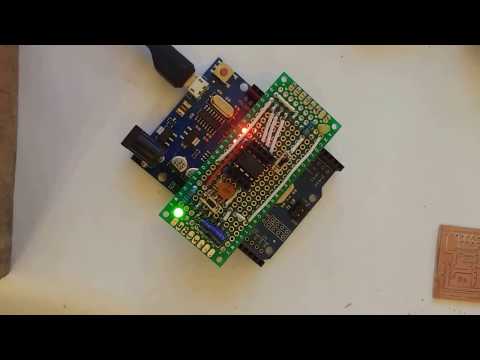](https://www.youtube.com/watch?v=rCrS0gHoqbE)
### ATtiny13/ATtiny13a/ATtiny25/ATtiny45/ATtiny85 ###
I really like the ATtiny, and for programmaer It, so I build a simple board to use ArduinoUNO as ISP in a faster way.
For Original ArduinoUNO there is a little variant because compatible one have another 5v VCC over RESET pin,
Arduino uno have IOREF instead.
(In project you can find fritzing file, the simple examples and schema).
## ATtiny13a variant
I buy ATtiny13a very low cost IC (less than 0.5€), with 4 analog pin and 2 PWM/TIMER PIN.


## How to program an ATtiny:
### Prepare ArduinoUNO to use it as ISP
1. In Arduino IDE select ArduinoUNO board (`Tool --> Board --> ArduinoUNO` - `Strumenti --> Scheda --> ArduinoUNO`);
2. Than open ArduinoISP example file (`File --> Examples/Esempi --> 11.ArduinoISP --> ArduinoISP`);
3. Upload Arduino (`Sketch --> Upload/Carica`);
4. Close IDE.
### Add support for ATtiny:
**ATtiny13/ATtiny13a** ([GitHub ATtiny13 support](https://github.com/MCUdude/MicroCore)):
1. Open the Arduino IDE;
2. Open the `File > Preferences` menu item;
3. Enter the following URL in Additional Boards Manager URLs: [`https://mcudude.github.io/MicroCore/package_MCUdude_MicroCore_index.json`](https://mcudude.github.io/MicroCore/package_MCUdude_MicroCore_index.json) ;
4. Open the `Tools > Board > Boards Manager`... menu item;
5. Wait for the platform indexes to finish downloading;
6. Scroll down until you see the MicroCore entry and click on it;
7. Click Install;
8. After installation is complete close the Boards Manager window.
**ATtiny25/ATtiny45/ATtiny85** ([GitHub other ATtiny support](https://github.com/damellis/attiny/))
1. Open the Arduino IDE;
2. Open the File > Preferences menu item;
3. Enter the following URL in Additional Boards Manager URLs: [`https://raw.githubusercontent.com/damellis/attiny/ide-1.6.x-boards-manager/package_damellis_attiny_index.json`](https://raw.githubusercontent.com/damellis/attiny/ide-1.6.x-boards-manager/package_damellis_attiny_index.json) ;
4. Open the Tools > Board > Boards Manager... menu item;
5. Wait for the platform indexes to finish downloading;
6. Scroll down until you see the MicroCore entry and click on it;
7. Click Install;
8. After installation is complete close the Boards Manager window.
### Upload to ATtiny
1. Attach board to ArduinoUNO;
2. Insert ATtinyXX;
3. If the board is v03 than activate test led otherwise using a breadboard and take VCC from upper right pin of attiny and GND to down left pin, than connect 0 pin (down right) to a led;
4. Select board with correct setting and PORT (`Tools --> Board/Strumenti --> Scheda`);
5. Select Arduino as ISP (`Tools --> Programmer --> Arduino as ISP/Strumenti --> Programmatore --> Arduino as ISP`);
`note: Arduino as ISP is different from ArduinoISP`.
6. Upload program (`Sketch --> Upload from programmer` / `Schetch --> Carica tramite un programmatore`).
### Sample sketch
```cpp
#define PIN 0
void setup()
{
pinMode(PIN, OUTPUT);
}
void loop()
{
digitalWrite(PIN, LOW);
delay(500);
digitalWrite(PIN, HIGH);
delay(500);
}
```
## Schema:
I use a [prefored board](https://www.aliexpress.com/item/10pcs-lot-3cm-x-7cm-Double-Side-prototype-pcb-3-7-Proto-Board/32685891618.html?spm=2114.search0104.3.1.q7TYLn&ws_ab_test=searchweb0_0,searchweb201602_3_10152_10065_10151_10344_10068_10345_10342_10343_10340_10341_10541_10084_10083_10304_10307_10177_5640015_5590015_10302_10060_10155_10154_10056_10055_10539_10538_5370015_10537_10312_10536_10059_10313_10184_10314_10534_10533_100031_10103_10073_10102_10142_10107,searchweb201603_30,ppcSwitch_2&btsid=0fc181c5-3d4e-4580-bf8d-0318e539854f&algo_expid=0158e307-1a76-404c-8a83-54b0cd5e7954-0&algo_pvid=0158e307-1a76-404c-8a83-54b0cd5e7954), and to switch Voltage and to enable test led I use a smd on/off button instead pin with jumper.
The board is double side so I can attach pin and componend up and down the board.
Board v01:

Board v01 (Original ArduinoUNO):

Board v02 (power led):

Board v03 (test led):

Schema v03 (test led):

## Material
## Assembly List
| Label | Part Type | Properties |
| --- | --- | --- |
| Arduino UNO | Arduino Uno (Rev3) | tipo Arduino UNO (Rev3) |
| Capacitor to prevent reset | Electrolytic Capacitor | capacitance 10µF |
| Capacitor to stabilize | Ceramic Capacitor | capacitance 100 nF |
| IC Holder | ICHold | pin spacing 300mil; pins 8 |
| Power led | Green (570nm) LED | package 3 mm [THT]; colore Green (570nm); leg yes |
| Test led | Yellow (595nm) LED | package 3 mm [THT]; colore Yellow (595nm); leg yes |
| Left arduino pin (from VIN) | Generic male header - 8 pins | package THT; form ♂ (male); hole size 1.0mm,0.508mm; pin spacing 0.1in (2.54mm); pins 8; row single |
| Left IC pin | Generic female header - 4 pins | package THT; form ♀ (female); hole size 1.0mm,0.508mm; pin spacing 0.1in (2.54mm); pins 4; row single |
| PullUp reset resistor | 10kΩ Resistor | package 2512 [SMD]; resistenza 10kΩ; tolerance ±5% |
| R1 | 220Ω Resistor | bands 4; package THT; resistenza 220Ω; pin spacing 400 mil; tolerance ±5% |
| R2 | 220Ω Resistor | bands 4; package THT; resistenza 220Ω; pin spacing 400 mil; tolerance ±5% |
| Right arduino pin (7) | Generic male header - 1 pins | package THT; form ♂ (male); hole size 1.0mm,0.508mm; pin spacing 0.1in (2.54mm); pins 1; row single |
| Right arduino pin (from 8) | Generic male header - 6 pins | package THT; form ♂ (male); hole size 1.0mm,0.508mm; pin spacing 0.1in (2.54mm); pins 6; row single |
| Right IC pin | Generic female header - 4 pins | package THT; form ♀ (female); hole size 1.0mm,0.508mm; pin spacing 0.1in (2.54mm); pins 4; row single |
| Jumper voltage setting | Generic male header - 3 pins | package THT; form ♂ (male); hole size 1.0mm,0.508mm; pin spacing 0.1in (2.54mm); pins 3; row single |
| Enable test led on PIN0 | Generic male header - 3 pins | package THT; form ♂ (male); hole size 1.0mm,0.508mm; pin spacing 0.1in (2.54mm); pins 3; row single |
## Shopping List
| Amount | Part Type | Properties |
| --- | --- | --- |
| 1 | Arduino Uno (Rev3) | tipo Arduino UNO (Rev3) |
| 1 | Electrolytic Capacitor | capacitance 10µF |
| 1 | Ceramic Capacitor | capacitance 100 nF |
| 1 | IC Holder | pin spacing 300mil; pins 8 |
| 1 | Green (570nm) LED | package 3 mm [THT]; colore Green (570nm); leg yes |
| 1 | Yellow (595nm) LED | package 3 mm [THT]; colore Yellow (595nm); leg yes |
| 1 | 10kΩ Resistor | package 2512 [SMD]; resistenza 10kΩ; tolerance ±5% |
| 2 | 220Ω Resistor | bands 4; package THT; resistenza 220Ω; pin spacing 400 mil; tolerance ±5% |
| | Generic male header | package THT; form ♂ (male); hole size 1.0mm,0.508mm; pin spacing 0.1in (2.54mm); pins 8; row single |
| | Generic female header | package THT; form ♀ (female); hole size 1.0mm,0.508mm; pin spacing 0.1in (2.54mm); pins 4; row single |
**ATtiny13a** [I used this for test](https://www.aliexpress.com/item/5Pcs-lot-ATTINY13A-PU-ATTINY13A-ATMEL-ATTINY13-13A-PU-IC-Free-shipping/2041732789.html?spm=2114.search0104.3.277.MJSnMS&ws_ab_test=searchweb0_0,searchweb201602_3_10152_10065_10151_10344_10068_10345_10342_10343_10340_10341_10541_10540_10084_10083_5370020_10304_10307_10177_10302_10060_10155_10154_10056_10055_10539_10538_10537_10312_10536_10059_10313_10184_10314_10534_10533_100031_10103_10073_10102_5590020_5640020_10142_10107,searchweb201603_30,ppcSwitch_2&btsid=271e5ab3-b1d0-4fc8-b0ce-b7d60e4ec24a&algo_expid=40a91871-0e14-4bd1-99fd-60b9e24f5f29-36&algo_pvid=40a91871-0e14-4bd1-99fd-60b9e24f5f29)
## Screen
Preforated board up:

Preforated board down:

Mount on Arduino:

After upload:
