Ecosyste.ms: Awesome
An open API service indexing awesome lists of open source software.
https://github.com/sgherbst/anasymod
A framework for FPGA emulation of mixed-signal systems
https://github.com/sgherbst/anasymod
Last synced: 3 months ago
JSON representation
A framework for FPGA emulation of mixed-signal systems
- Host: GitHub
- URL: https://github.com/sgherbst/anasymod
- Owner: sgherbst
- License: bsd-3-clause
- Created: 2019-03-25T16:57:48.000Z (over 5 years ago)
- Default Branch: master
- Last Pushed: 2021-07-28T17:00:35.000Z (almost 3 years ago)
- Last Synced: 2024-03-18T02:41:38.801Z (4 months ago)
- Language: Python
- Homepage:
- Size: 969 KB
- Stars: 31
- Watchers: 8
- Forks: 9
- Open Issues: 21
-
Metadata Files:
- Readme: README.md
- License: LICENSE
Lists
- awesome-opensource-hardware - anasysmod
- awesome-eda - A framework for FPGA emulation of mixed-signal systems
README
# anasymod
[](https://github.com/sgherbst/anasymod/actions)
[](https://buildkite.com/stanford-aha/anasymod)
[](https://codecov.io/gh/sgherbst/anasymod)
[](https://opensource.org/licenses/BSD-3-Clause)
[](https://gitter.im/sgherbst/anasymod?utm_source=badge&utm_medium=badge&utm_campaign=pr-badge&utm_content=badge)
**anasymod** is a tool for running FPGA emulations of mixed-signal systems. It supports digital blocks described with Verilog or VHDL and synthesizable analog models created using [msdsl](https://github.com/sgherbst/msdsl) and [svreal](https://github.com/sgherbst/svreal).
# Installation
## From PyPI
```shell
> pip install anasymod
```
If you get a permissions error when running one of the **pip** commands, you can try adding the **--user** flag to the **pip** command. This will cause **pip** to install packages in your user directory rather than to a system-wide location.
## From GitHub
If you are a developer of **anasymod**, it is more convenient to clone and install the GitHub repository:
```shell
> git clone https://github.com/sgherbst/anasymod.git
> cd anasymod
> pip install -e .
```
## Testing the Installation
Check to see if the **anasymod** command-line script is accessible by running:
```shell
> anasymod -h
```
If the **anasymod** script isn't found, then you'll have to add the directory containing it to the path. On Windows, a typical location is **C:\\Python3\*\\Scripts**, while on Linux or macOS you might want to check **~/.local/bin** (particularly if you used the **--user** flag).
# Prerequites to run the examples
The examples included with **anasymod** use [Icarus Verilog](http://iverilog.icarus.com) for running simulations, [Xilinx Vivado](https://www.xilinx.com/products/design-tools/vivado.html) for running synthesis and place-and-route, and [GTKWave](http://gtkwave.sourceforge.net) for viewing the simulation and emulation results. The instructions for setting up these tools are included below for various platforms.
## Windows
Install Xilinx Vivado by going to the [downloads page](https://www.xilinx.com/support/download.html). Scroll to the latest version of the "Full Product Installation", and download the Windows self-extracting web installer. Launch the installer and follow the instructions. You'll need a Xilinx account (free), and will have to select a license, although the free WebPACK license option is fine you're just planning to work with small FPGAs like the one on the Pynq-Z1 board.
GTKwave and Icarus Verilog can be installed at the same time using the latest Icarus binary [here](http://bleyer.org/icarus/).
## Linux
Install Xilinx Vivado by going to the [downloads page](https://www.xilinx.com/support/download.html). Scroll to the latest version of the "Full Product Installation", and download the Linux self-extracting web installer. Then, in a terminal:
```shell
> sudo ./Xilinx_Vivado_SDK_Web_*.bin
```
A GUI will pop up and guide you through the rest of the installation. Note that you'll need a Xilinx account (free), and that you can select the free WebPACK license option if you're planning to work with relatively small FPGAs like the one on the Pynq-Z1 board.
Next, the Xilinx cable drivers must be installed ([AR #66440](https://www.xilinx.com/support/answers/66440.html)):
```shell
> cd /data/xicom/cable_drivers/lin(32|64)/install_script/install_drivers
> sudo ./install_drivers
```
Finally, some permissions cleanup is required ([AR #62240](https://www.xilinx.com/support/answers/62240.html))
```shell
> cd ~/.Xilinx/Vivado
> sudo chown -R $USER *
> sudo chmod -R 777 *
> sudo chgrp -R $USER *
```
Installing GTKWave and Icarus Verilog is much simpler; just run the following in a terminal:
```shell
> sudo apt-get install gtkwave iverilog
```
## macOS
The simulation part of this example should work if you install Icarus Verilog and GTKWave:
```shell
> brew install icarus-verilog
> brew install --cask gtkwave
```
Unfortunately Xilinx Vivado does not run natively on macOS. However, running Vivado on a Windows or Linux virtual machine on macOS does seem to work.
## Running a Simulation
From within the folder **unittests**, run
```shell
> anasymod -i buck --models --sim --view
```
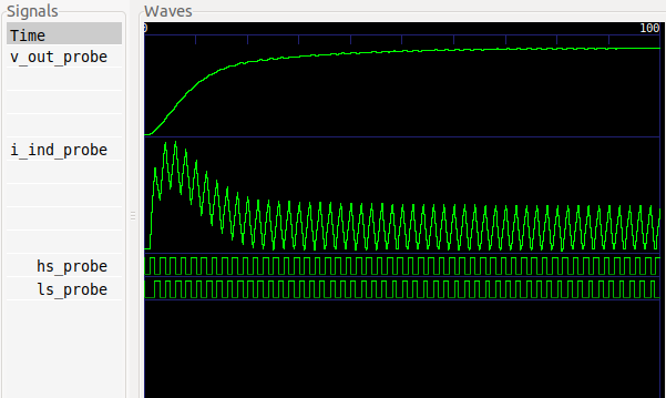
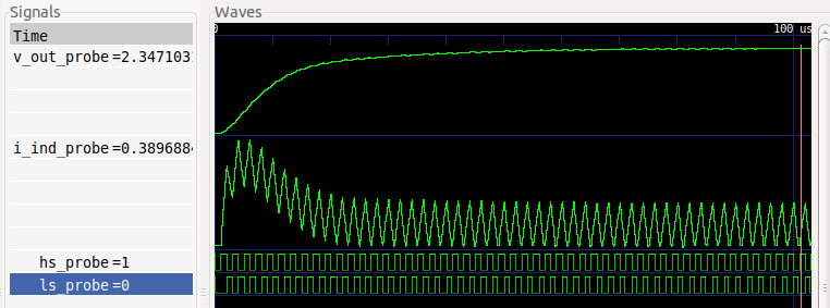
This will generate a synthesizable model for a buck converter, run a simulation, and display the results.
### Command-line options
Here's a breakdown of what the options mean:
* The **-i buck** option indicates that the folder ``buck`` contains the emulation files
* **--models** means that **anasymod** should look for a file called **gen.py** and run it. In this case the **gen.py** script uses [msdsl](https://git.io/msdsl) to generate a synthesizable model for the buck converter.
* **--sim** means that a simulation should be run on the computer, rather than building the emulator bitstream. This is helpful for debugging. You can also pass the option **--simulator_name NAME** to specify which simulator should be used. Currently supported simulators are **icarus**, **vivado**, and **xrun** (Cadence Xcelium),
* **--view** means that the resuls should be displayed after running the simulation. The viewer can be specified with the **--viewer_name NAME** option. Only **gtkwave** is supported at the moment. When a file called **view.gtkw** is in the folder with emulator sources, **anasymod** will load it to configure the GTKWave display. You can generate your own **view.gtkw** file using ``File`` → ``Write Save File`` in GTKWave.
### Source files
Looking into the ``buck`` folder, you'll notice there are a bunch of files. Some have special meanings for the **anasymod** tool (i.e., if you have a file with one of these names, it **anasymod** will treat it in a certain way)
* ``gen.py``: Generates synthesizable emulation models. **anasymod** expects to run this as a command-line script that has arguments ``-o`` (output directory) and ``-dt`` (fixed timestep). **anasymod** fills those arguments based on user settings when it runs **gen.py**.
* ``prj.yaml``: YAML file containing settings for the project, like the FPGA board to use, build options, emulator control infrastructure to use, etc. In this case, one of the key options is **dt**, which indicates that each emulator cycle corresponds to a fixed timestep of 50 ns.
* ``simctrl.yaml``: YAML file containing signals to probe. The signals indicated will be probed for both simulation and emulation (in the latter case, using a Xilinx Integrated Logic Analyzer instance). This file can also specify signals to be written and read in interactive tests.
* ``tb.sv``: Top-level file for simulation and synthesis, representing a synthesizable testbench.
**anasymod** has other special files (e.g., ``clks.yaml` for controlling clock generation), but they are not used in this example.
## Running an Emulation
At this point, we have run a simulation of the emulator design, but haven't built a bitstream of programmed the FPGA. This section shows how to run those tasks.
For this test to work as-is, you'll need a [Pynq-Z1](https://store.digilentinc.com/pynq-z1-python-productivity-for-zynq-7000-arm-fpga-soc/) board. However, if you uncomment the ``board_name`` option in ``prj.yaml``, you can specify a different board; currently supported options are ``PYNQ_Z1``, ``ARTY_A7``, ``VC707``, ``ZC702``, ``ZC706``, ``ZCU102``, and ``ZCU106``. We are always interested to add support for new boards, so please let us know if your board isn't listed here (feel free to file a GitHub Issue).
Go to the folder **unittests** and run the following command. It will take about 11 minutes to build the bitstream.
```shell
> anasymod -i buck --models --build
```
If you are using the Pynq-Z1 board, then please make sure it is set up correctly:
1. Jumper JP4 should be set for "JTAG"
2. Jumper "JP5" should be set for "USB"
Then, plug the Pynq board into your computer using a micro USB cable. Move the Pynq board power switch to "ON".
Run the emulation and view the results with the following command:
```shell
> anasymod -i buck --emulate --view
```
For now, there is a separate ``*.gtkw`` file used when viewing emulation results, which is ``view_fpga.gtkw``.
## Timestep Management
The example considered so far used a fixed timestep, but for optimal emulator performance, some systems benefit from an event-driven approach, where various blocks make timestep requests, resulting in a variable timestep emulator.
With **anasymod**, an emulation model can make a timestep request (``dt_req``), which is passed to an auto-generated time manager. The time manager takes the minimum of all timestep requests, and passes the result (``emu_dt``) back to models that need that information.
This system is configured through a file called ``clks.yaml``. For an example, see ``unittests/multi_clock``, which represents a system where two independent oscillators are running at different frequencies, and each is making its own timestep requests.
If you look in the top-level file (``tb.sv``), you'll see that there are two oscillator instances, ``osc_0`` and ``osc_1``. These are referenced in ``clks.yaml``, which says that **anasymod** should wire up the timestep request from each (``dt_req``) as well as the emulator timestep (``emu_dt``). It also connects up the emulator clock (``emu_clk``) and reset signals (``emu_rst``).
This brings us to a point about postprocessing: when you run a simulation or emulation, the raw data produced is dumped to a folder called ``raw_results``, and includes a timestamp at each emulation cycle. To make the results easier to visualize, **anasymod** post-processes the raw data, applying timestamps to all signals. The post-processed result is placed in a folder called ``vcd``; that waveform is what is displayed when you invoke the **--view** option. However, for debugging timestep issues, it can be useful to examine the ``raw_results`` folder, too.
## Clock Generation
The same ``clks.yaml`` file also handles the generation of new clock signals. **anasymod** automatically generates an emulator clock signal, but typically there are one or more "real" clocks in the design that need to be generated as well.
This takes some care to avoid timing issues, and the strategy taken by **anasymod** is to make sure the rising and falling edges of all generated clocks are aligned to a rising edge of the emulator clock. For a block that wants to generate a new clock signal, it produces a clock request (``gated_clk_req``) in the preceding emulator cycle, like a clock enable signal, and **anasymod** passes the generated clock signal (``gated_clk``) back to the block. The generated clock is properly aligned and routed through FPGA clock infrastructure to ensure good performance.
You can see an example of this configuration by examing the ``clk_0`` and ``clk_1`` entries in ``clks.yaml`` of the ``multi_clock`` example: the oscillator models each produce a clock request, and each clock request is used to generate one clock signal.
## Firmware
Rather than writing tests entirely in RTL, or controlling tests entirely from a host computer, it is often a good compromise to use firmware running on the FPGA to receive commands from the host computer and implement them at a lower level when interacting with the code in ``tb.sv``.
For FPGAs that contain a Processing System (PS), **anasymod** automates much of this process by automatically instantiating the PS and generating firmware to interact with it. An example can be seen in ``unittests/custom_firmware``, where user code, written in ``main.c`` invokes ``GET`` and ``SET`` commands from the auto-generated``gpio_funcs.h`` header.
The signals to be set up for reading and writing are specified in ``simctrl.yaml``, just as they would be for VIO-based control. However, the ``fpga_sim_ctrl`` setting in ``prj.yaml`` indicates that VIO control should not be used, and that the FPGA should instead using PS firmware to interact with the DUT.
By default, **anasymod** will generate a ``main.c`` file, but if you want to use your own, as in this example, set ``custom_zynq_firmware`` to ``True`` in ``prj.yaml``, and then specify the location of the ``main.c`` file in ``source.yaml`` (under ``firmware_files``).
## Interactive Tests
It's often important to be able to interact with the emulator from Python while it is running, is order to steer the high-level direction of the tests. This is supported through the ``Analysis`` object provided by the **anasymod** Python package, which provides a programmatic way to access all of the features of the command-line **anasymod** tool.
As an example, consider the example in ``unittests/rc``, which is an RC filter whose input and output are accessible for interactive testing (as specifed in its ``simctrl.yaml`` file).
With the **anasymod** programmatic interface, it's possible to build a bitstream, program the FPGA, and interact with the emulator with a fairly small number of lines of code:
```python
from anasymod.analysis import Analysis
ana = Analysis('path/to/rc')
ana.set_target('fpga')
ana.build() # build bitstream
ctrl = ana.launch() # program FPGA
ctrl.stall_emu()
ctrl.set_param(name='v_in', value=1.0)
ctrl.set_reset(1)
ctrl.set_reset(0)
for _ in range(25):
ctrl.refresh_param('vio_0_i')
v_out = ctrl.get_param('v_out')
t = ctrl.get_emu_time()
print(f't: {t}, v_out: {v_out}')
ctrl.sleep_emu(0.1e-6)
```
In real-world use, it's unlikely that you would want to rebuild the FPGA bitstream before every emulation run, but we have have included the command here just for reference. As long as the FPGA bitstream is built, you could comment out that line, and everything should still work.
This example illustrates how **anasymod** provides commands for interacting with emulator time (``stall_emu``, ``get_emu_time``, ``sleep``), as well as reading/writing emulator values (``set_param``, ``get_param``). Emulator I/O works for both digital values and analog values; in the analog case, it automatically converts real numbers to the format being used by the emulator.
## Contributing
To improve the quality of the software, users are encouraged to share modifications, enhancements or bug fixes with Infineon Technologies AG under [email protected].